Busbar system POWERTECH™
Introduction
In a world that evolves daily, the use of advanced technologies and innovative solutions is important to offer the best possible product. For this reason DKC has studied and implemented the new busbar product POWERTECH, respecting the guidelines imposed by the new international standard IEC 61439-6 The busbar POWERTECH, arose from the growing demand in the market for a good product, versatile and technological, but at the same time "easy" and safe for the energy distribution.
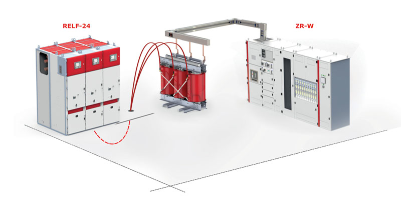
It Is particularly suitable in cabin, as connection transformer - switchboard or switchboard-switchboard, or for distribution of main power for industrial sector, commercial sector or services. POWERTECH has been designed to be modified directly on site. This unique solution allows to transform standard straight elements into special lengths busbars, reducing the risk of errors made, shortening the delivery time and realization period.
From design to implementation, using high quality materials and advanced technologies, all in one purpose - to put the POWERTECH busbar at the forefront of the busbars category.
General description
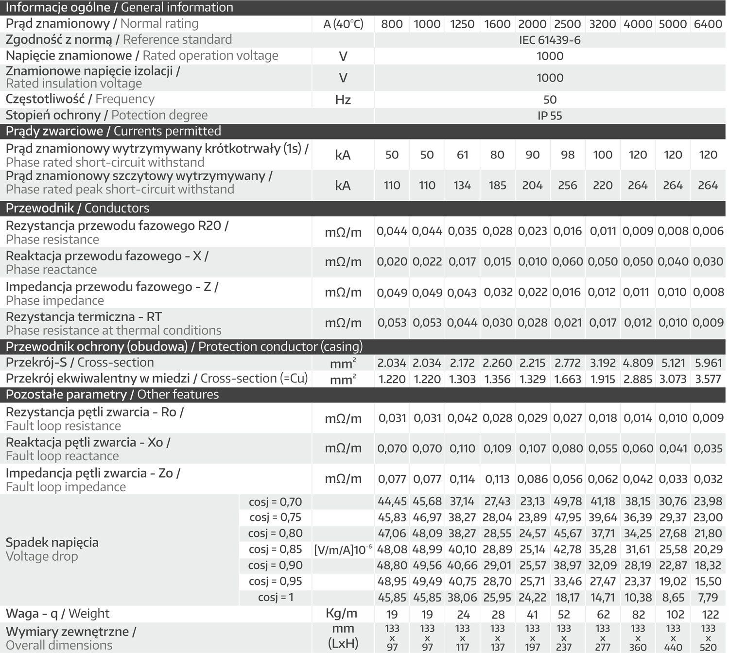
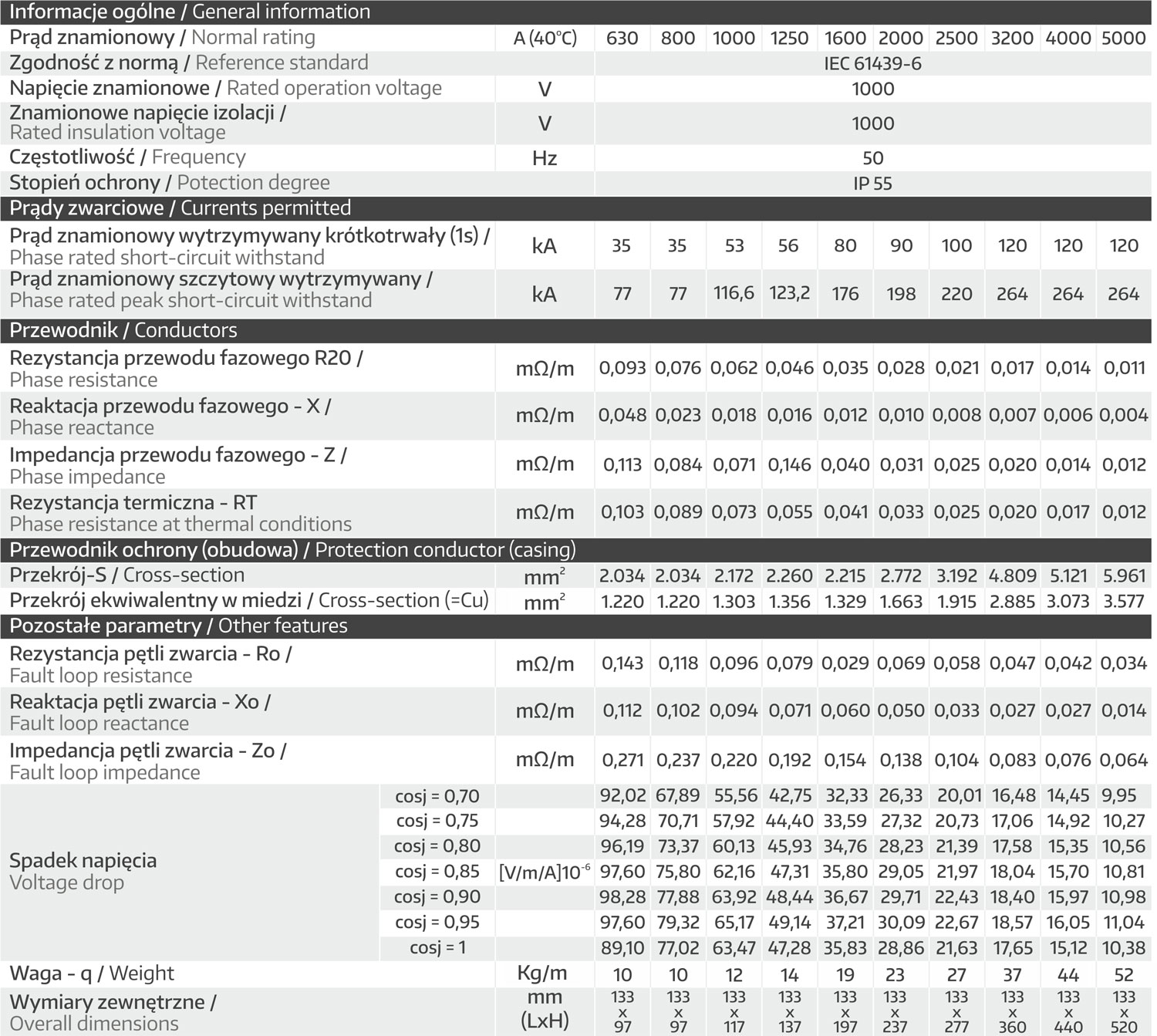
The POWERTECH busbar trunkings system conforms to IEC 61439 - 6 standards and is offered with nominal current from 630A to 5000A with aluminum conductors, while the nominal current is from 1000A to 6400A with copper conductors. In standard versions aluminium conductors are galvanically tinplated along their entire length to avoid oxidation problems, while copper conductors are not treated because the ETP 99.9 pure copper is used. On request, the copper conductors can be galvanically tinplated as well. For both versions (copper and aluminium)it is possible to have galvanically silver-plated conductors.
The standard product is offered in the 3P + N + PE (4 conductors) version with the neutral and the phase of the same cross-section and the casing as earth conductor with a cross-section that is more than 100% of the phase one. In order to satisfy the market requirements, A five conductor version is produced: the three phases and the neutral have the same cross-section, while the fifth conductor can be realized with a 50% of the phases cross-section and be used as CE (Clean Earth) or with 100% of the phases cross-section and be used to realize the 200% cross-section neutral version or as dedicate earth bar.
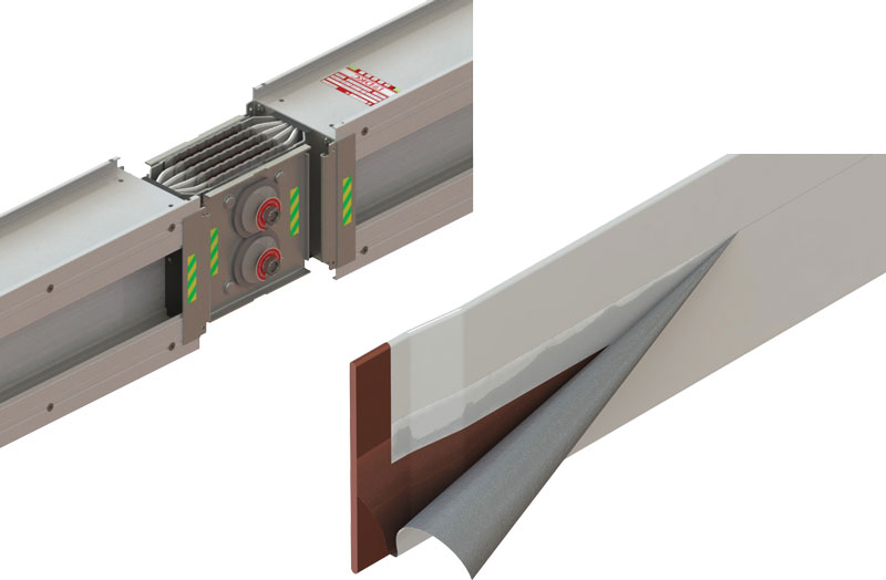
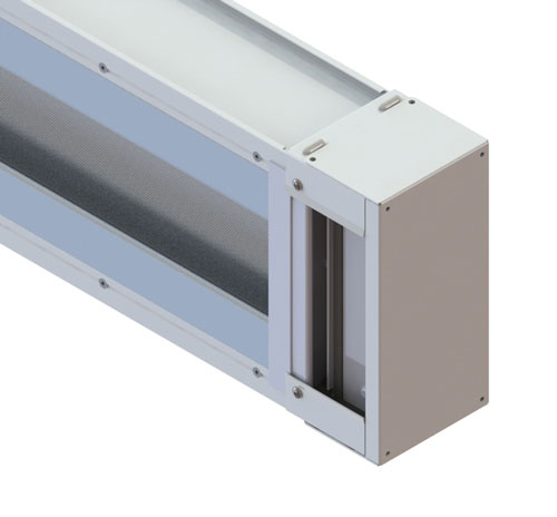
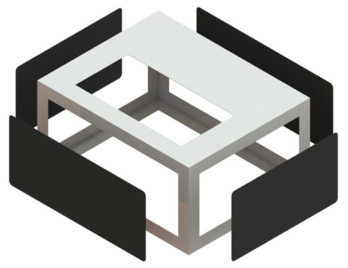
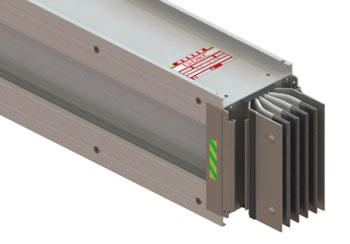
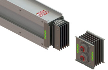
According to the nominal current the phases and the neutral are realized with one or two bars: in the two bars version, they are connected to each joint cover unit between two trunking units. The casing is made of aluminium alloy extruded profile giving the product high mechanical resistance and a large reduction in weight compared to a casing made of galvanized sheet steel. The electrical and mechanical connection is achieved thanks to a monoblock system with one or more bolts (depending on the busbar trunkings rated current) and self-breakable nuts that can be easily and quickly installed without the help of any special tool (torque wrench). POWERTECH busbar trunkings system standard version is offered with RAL7035 painting (other paintings are possible if requested), the protection degree is IP55. For outdoor installations extra protection is recommended.
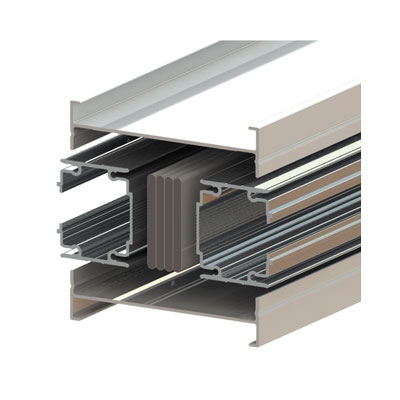
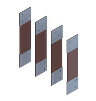
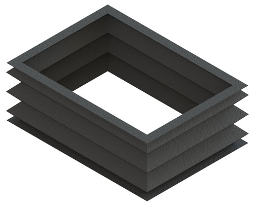
POWERTECH busbar trunking system is made in sandwich technology (compact); the conductor bars are compacted without any room inside the casing and are fully insulated with DyTerm® insulator obtained by a combination of a polyester sheet together with Nomex® (Dupont®) which complies to 2011/65/UE (RoHS) European Directive (entered into force on 3rd January 2013) and with a "F" thermic class 155°C (for special achievements insulators with a "H" thermic class up to 180°C can be used). All these characteristics guarantee POWERTECH busbar trunkings system high electrical performances thanks to the reduction of magnetic fields and voltage drop values even in high current and long distances extreme conditions. The product offers excellent technical performance with a high mechanical resistance, high resistance to weathering in particularly aggressive environments.
Configurations
(4 conductors)
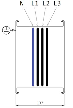
The protective conductor is made from aluminium casing with cross section equal or grater than the cross section of the phase conductor.
(5 conductors)
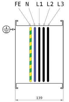
The protective conductor is made as a dedicated bar inside the duct with the same section and material as the phase conductor.
(5 conductors)
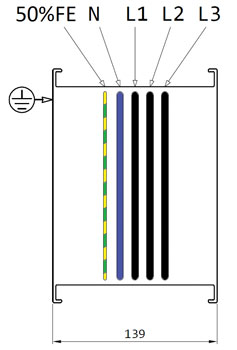
The protective conductor is made as a dedicated bar inside the duct with the section equal to 50% of that phase conductor.
(5 conductors)
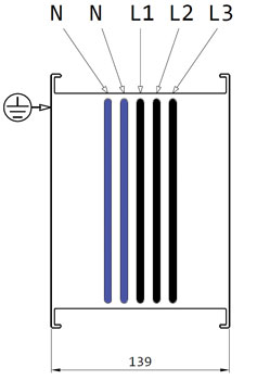
The neutral conductor has double section against to the phase conductor.
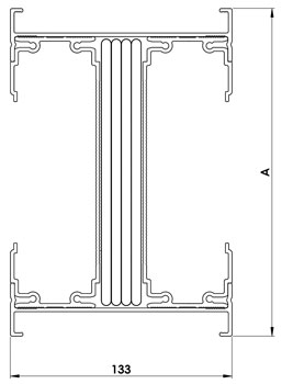
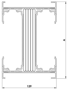
| Aluminium | Copper | |||
| Rating | Dim. (mm) |
Rating | Dim. (mm) |
|
| Single | 800 A | 98 | 1000 A | 98 |
| 1000 A | 118 | 1250 A | 118 | |
| 1250 A | 138 | 1600 A | 138 | |
| 1600 A | 198 | 2000 A | 198 | |
| 2000 A | 238 | 2500 A | 238 | |
| 2500 A | 278 | 3200 A | 278 | |
| Double | 3200 A | 363,5 | 4000 A | 232,5 |
| 4000 A | 443,5 | 5000 A | 443,5 | |
| 5000 A | 523,5 | 6000 A | 523,5 | |

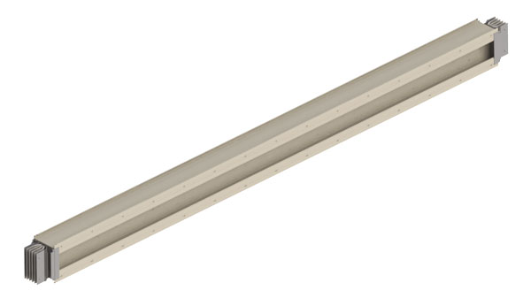
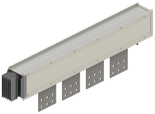
Trunking elements
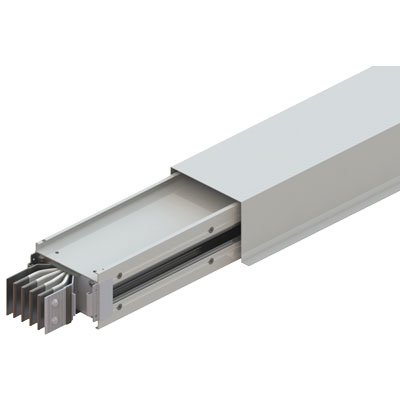
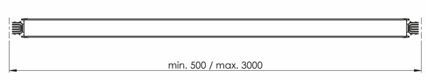
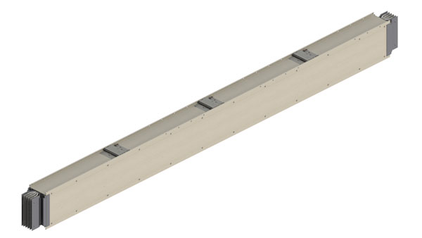
Straight element
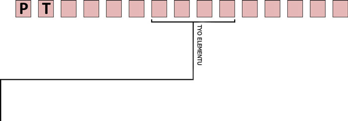
A transport straight trunking element. It is available in lenght between 500mm and 3000mm.
- SEF1 = Straight element standard 3000mm
- SEF2 = Special straight element < 3000mm
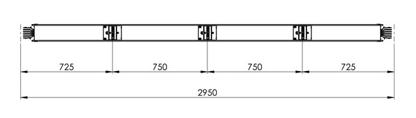
Straight element with tap-off box facilities
Straight elements equipped with slots for tap-off boxes till 630A.
- SP11 = Standard straight element with tap-off facilities ≤ 2950mm - 3 tap-off facilities from one side – spaces 725/750/750/725
- SP12 = Special straight element with tap-off facilities ≤ 2950mm - 3 tap-off facilities from one side – special interspaces
- SP13 = Special straight element with tap-off facilities ≤ 2950mm - 2 tap-off facilities from one side – special interspaces
- SP14 = Special straight element with tap-off facilities ≤ 2950mm - 1 tap-off facilities from one side – special interspaces
- SP15 = Special straight element with tap-off facilities ≤ 2950mm - 4 tap-off facilities from one side – special interspaces
- SP16 = Standard straight element with tap-off facilities in vert. runs≤ 2400mm - 2 tap-off facilities from one side – special interspaces
- SP21 = Special straight element with tap-off facilities ≤ 2950mm - 3+3 tap-off facilities from both side – spaces 725/750/750/725
- SP22 = Special straight element with tap-off facilities ≤ 2950mm - 3+3 tap-off facilities from both side – special interspaces
- SP23 = Straight element for distribution spec. ≤ 2950 - 2+2 tap off facilities 2 sides - special interspace
- SP24 = Special straight element with tap-off facilities ≤ 2950mm - 1+1 tap-off facilities from both side – special interspaces
- SP25 = Special straight element with tap-off facilities ≤ 2950mm - 4+4 tap-off facilities from both side – special interspaces
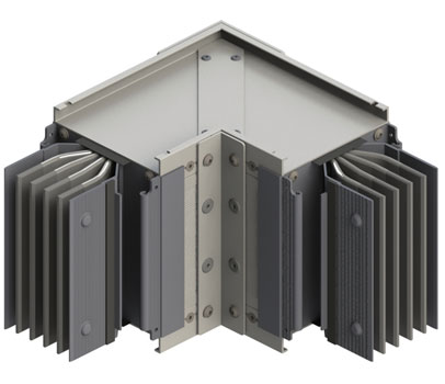
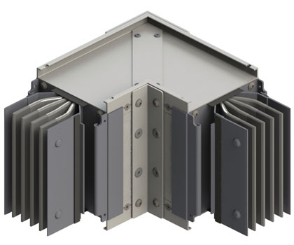
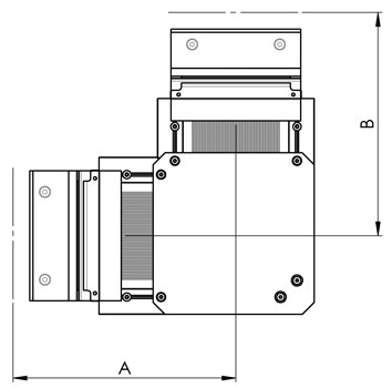
Horizontal elbow
Element that allows to change direction horizontally
- HEL1 = Horizontal elbow type 1 – standard
- HEL2 = Horizontal elbow type 2 – standard
- HEL3 = Horizontal elbow type 1 – special
- HEL4 = Horizontal elbow type 2 – special
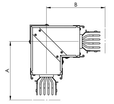
| STANDARD DIMENSIONS | |||
| A | B | ||
| B60 | 250 | 250 | |
| B80 | 250 | 250 | |
| B100 | 250 | 250 | |
| B160 | 250 | 250 | |
| B200 | 250 | 250 | |
| B240 | 250 | 250 | |
| 2B160 | 250 | 250 | |
| 2B200 | 250 | 250 | |
| 2B240 | 250 | 250 | |
| MAXIMUM DIMENSIONS | |||
| A | B | ||
| B60 | 749 | 749 | |
| B80 | 749 | 749 | |
| B100 | 749 | 749 | |
| B160 | 749 | 749 | |
| B200 | 749 | 749 | |
| B240 | 749 | 749 | |
| 2B160 | 749 | 749 | |
| 2B200 | 749 | 749 | |
| 2B240 | 749 | 749 | |
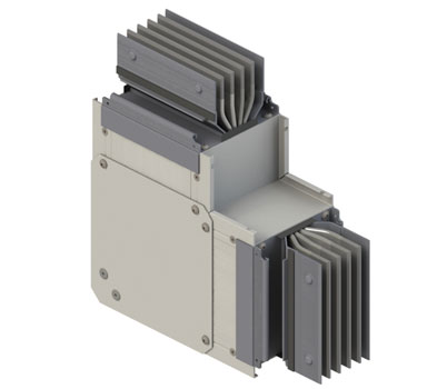
Vertical elbow
Element that allows to change direction vertically.
- VEL1 = Vertical elbow standard
- VEL2 = Vertical elbow special
| STANDARD DIMENSIONS | |||
| A | B | ||
| B60 | 230 | 230 | |
| B80 | 240 | 240 | |
| B100 | 250 | 250 | |
| B160 | 280 | 280 | |
| B200 | 300 | 300 | |
| B240 | 320 | 320 | |
| 2B160 | 370 | 370 | |
| 2B200 | 410 | 410 | |
| 2B240 | 450 | 450 | |
| MAXIMUM DIMENSIONS | |||
| A | B | ||
| B60 | 729 | 729 | |
| B80 | 739 | 739 | |
| B100 | 749 | 749 | |
| B160 | 779 | 779 | |
| B200 | 799 | 799 | |
| B240 | 719 | 819 | |
| 2B160 | 869 | 869 | |
| 2B200 | 909 | 909 | |
| 2B240 | 949 | 949 | |
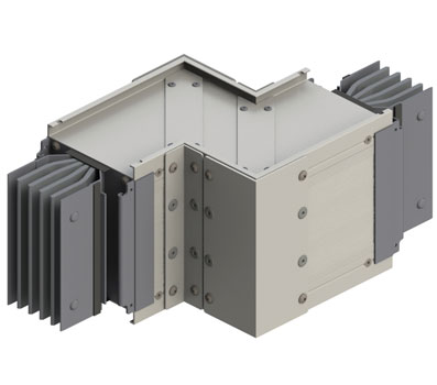
Horizontal elbow
Element that allows double change of direction horizontally.
To be applied when there is no sufficient space to joint two horizontal elbows.
- DHE1 = Double horizontal elbow type 1
- DHE2 = Double horizontal elbow type 1
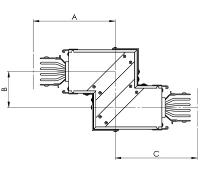
| STANDARD DIMENSIONS | |||
| A | B | C | |
| B60 | 250 | 70 | 250 |
| B80 | 250 | 70 | 250 |
| B100 | 250 | 70 | 250 |
| B160 | 250 | 70 | 250 |
| B200 | 250 | 70 | 250 |
| B240 | 250 | 70 | 250 |
| 2B160 | 250 | 70 | 250 |
| 2B200 | 250 | 70 | 250 |
| 2B240 | 250 | 70 | 250 |
| MAXIMUM DIMENSIONS | |||
| A | B | C | |
| B60 | 749 | 449 | 749 |
| B80 | 749 | 449 | 749 |
| B100 | 749 | 449 | 749 |
| B160 | 749 | 449 | 749 |
| B200 | 749 | 449 | 749 |
| B240 | 749 | 449 | 749 |
| 2B160 | 749 | 449 | 749 |
| 2B200 | 749 | 449 | 749 |
| 2B240 | 749 | 449 | 749 |
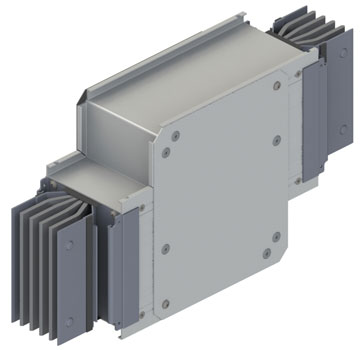
Horizontal elbow
Element that allows double change of direction vertically.
To be applied when there is no sufficient space to joint two
vertical elbows.
- DVE1 = Double vertical elbow type 1
- DVE2 = Double vertical elbow type 2
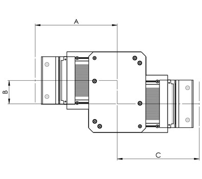
| STANDARD DIMENSIONS | |||
| A | B | C | |
| B60 | 230 | 80 | 230 |
| B80 | 240 | 80 | 240 |
| B100 | 250 | 80 | 250 |
| B160 | 280 | 80 | 280 |
| B200 | 300 | 80 | 300 |
| B240 | 320 | 80 | 320 |
| 2B160 | 370 | 80 | 370 |
| 2B200 | 410 | 80 | 410 |
| 2B240 | 450 | 80 | 450 |
| MAXIMUM DIMENSIONS | |||
| A | B | C | |
| B60 | 729 | 459 | 729 |
| B80 | 739 | 479 | 739 |
| B100 | 749 | 499 | 749 |
| B160 | 779 | 559 | 779 |
| B200 | 799 | 599 | 799 |
| B240 | 819 | 639 | 819 |
| 2B160 | 869 | 739 | 869 |
| 2B200 | 909 | 819 | 909 |
| 2B240 | 949 | 899 | 949 |
Double elbow horizontal + vertical
Element that allows double change of direction horizontally and vertically.
To be applied when there is no sufficient space to joint two elbows.
- HVE1 = Double elbow horizontal + vertical type 1
- HVE2 = Double elbow horizontal + vertical type 2
- HVE3 = Double elbow horizontal + vertical type 3
- HVE4 = Double elbow horizontal + vertical type 4
| STANDARD DIMENSIONS | |||
| A | B | C | |
| B60 | 749 | 479 | 729 |
| B80 | 749 | 489 | 739 |
| B100 | 749 | 499 | 749 |
| B160 | 749 | 429 | 779 |
| B200 | 749 | 549 | 799 |
| B240 | 749 | 569 | 819 |
| 2B160 | 749 | 619 | 869 |
| 2B200 | 749 | 659 | 909 |
| 2B240 | 749 | 699 | 949 |
| MAXIMUM DIMENSIONS | |||
| A | B | C | |
| B60 | 250 | 180 | 230 |
| B80 | 250 | 190 | 240 |
| B100 | 250 | 200 | 250 |
| B160 | 250 | 230 | 280 |
| B200 | 250 | 250 | 300 |
| B240 | 250 | 270 | 320 |
| 2B160 | 250 | 315 | 370 |
| 2B200 | 250 | 355 | 410 |
| 2B240 | 250 | 395 | 450 |
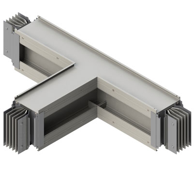
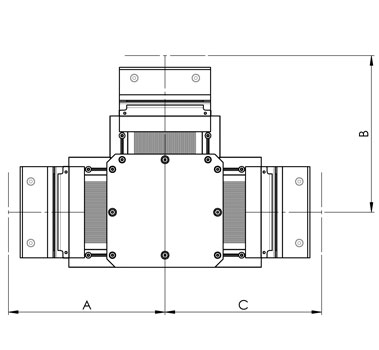
Horizontal tee
Tee element that divides horizontally the run in two lines of the same size and rating
- HTE1 = Horizontal tee type 1
- HTE2 = Horizontal tee type 2
- HTE5 = Horizontal tee type 1 special
- HTE6 = Horizontal tee type 2 special
| STANDARD DIMENSIONS | |||
| A | B | C | |
| B60 | 500 | 500 | 500 |
| B80 | 500 | 500 | 500 |
| B100 | 500 | 500 | 500 |
| B160 | 500 | 500 | 500 |
| B200 | 600 | 600 | 600 |
| B240 | 600 | 600 | 600 |
| 2B160 | 600 | 600 | 600 |
| 2B200 | 600 | 600 | 600 |
| 2B240 | 600 | 600 | 600 |
| MAXIMUM DIMENSIONS | |||
| A | B | C | |
| B60 | 999 | 999 | 999 |
| B80 | 999 | 999 | 999 |
| B100 | 999 | 999 | 999 |
| B160 | 999 | 999 | 999 |
| B200 | 999 | 999 | 999 |
| B240 | 999 | 999 | 999 |
| 2B160 | 999 | 999 | 999 |
| 2B200 | 999 | 999 | 999 |
| 2B240 | 999 | 999 | 999 |
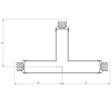
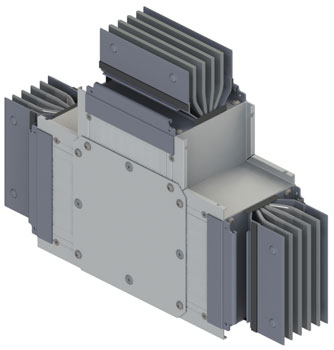
Vertical tee
Tee element that divides vertically the run in two lines of the same size and rating.
- VTE1 = Vertical tee
- VTE2 = Vertical tee special
| STANDARD DIMENSIONS | |||
| A | B | C | |
| B60 | 230 | 230 | 230 |
| B80 | 240 | 240 | 240 |
| B100 | 250 | 250 | 250 |
| B160 | 280 | 280 | 280 |
| B200 | 300 | 300 | 300 |
| B240 | 320 | 320 | 320 |
| 2B160 | 370 | 370 | 370 |
| 2B200 | 410 | 410 | 410 |
| 2B240 | 450 | 450 | 450 |
| MAXIMUM DIMENSIONS | |||
| A | B | C | |
| B60 | 729 | 729 | 729 |
| B80 | 739 | 739 | 739 |
| B100 | 749 | 749 | 749 |
| B160 | 779 | 779 | 779 |
| B200 | 799 | 799 | 799 |
| B240 | 819 | 819 | 819 |
| 2B160 | 869 | 869 | 869 |
| 2B200 | 909 | 909 | 909 |
| 2B240 | 949 | 949 | 949 |
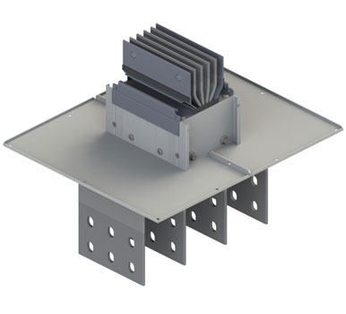
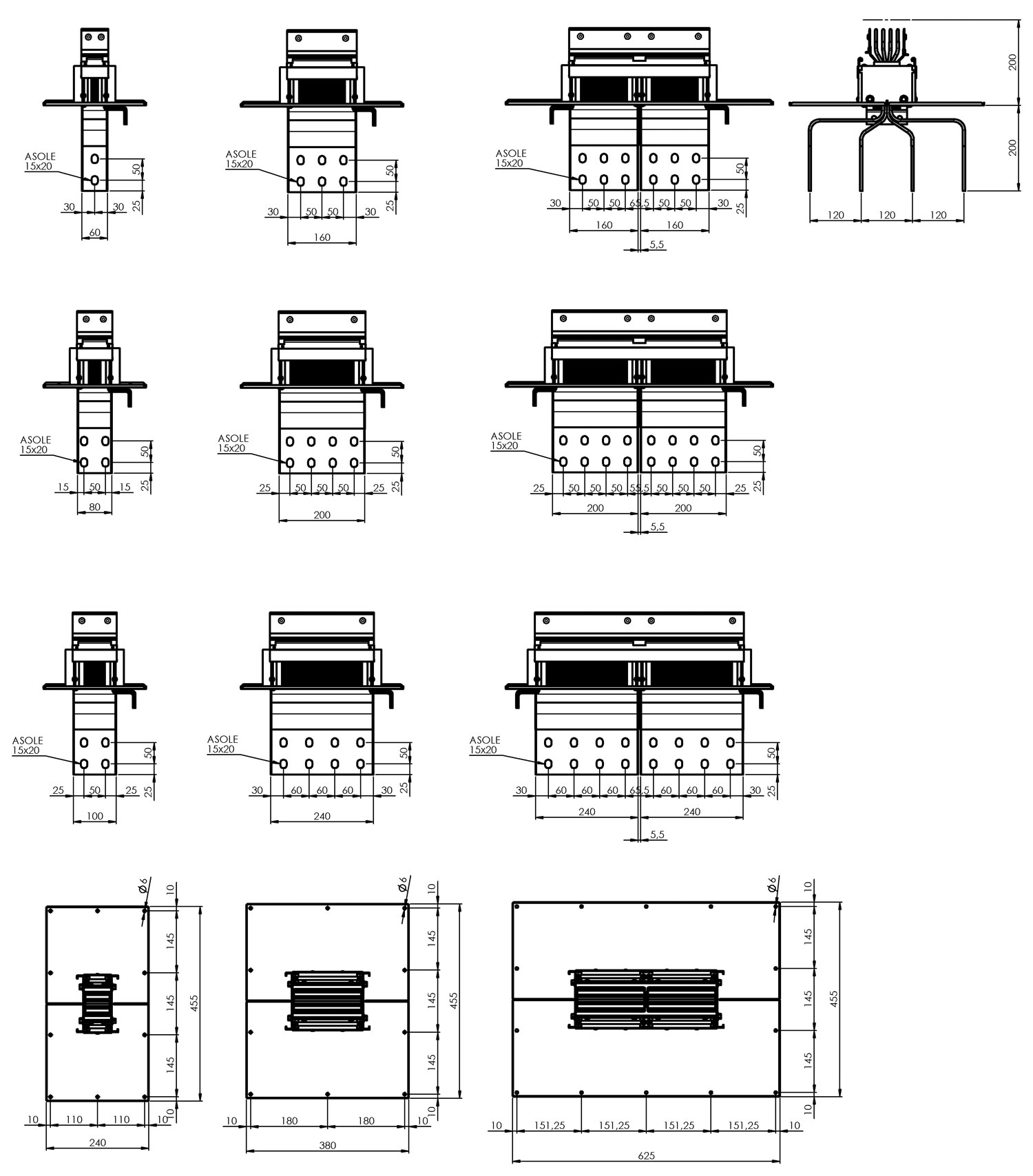
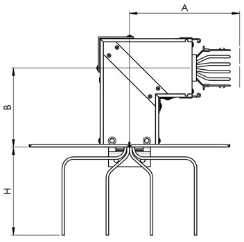
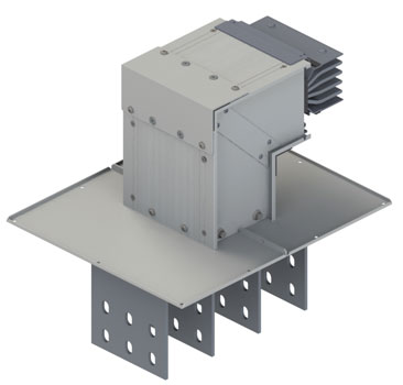
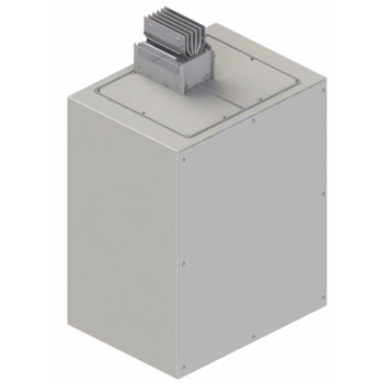
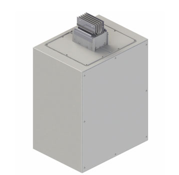
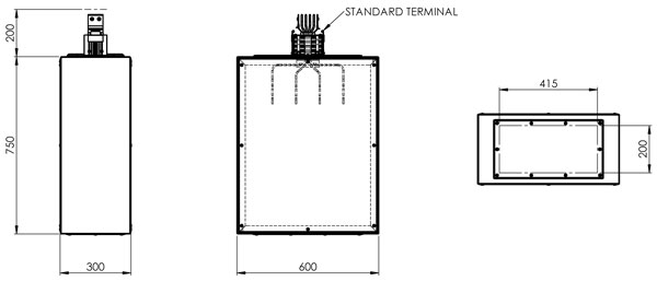
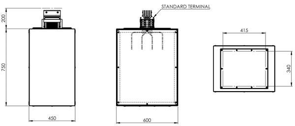
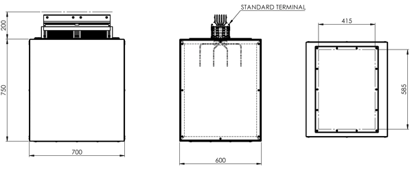
Terminal unit
Terminal connection to switchboard or transformers.
- TST1 = Terminal unit standard
- TST2 = Terminal unit special
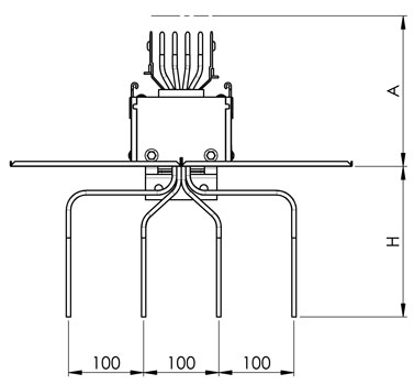
| STANDARD DIMENSIONS | ||
| A | H | |
| B60 | 200 | 200 |
| B80 | 200 | 200 |
| B100 | 200 | 200 |
| B160 | 200 | 200 |
| B200 | 200 | 200 |
| B240 | 200 | 200 |
| 2B160 | 200 | 200 |
| 2B200 | 200 | 200 |
| 2B240 | 200 | 200 |
| MAXIMUM DIMENSIONS | ||
| A | H | |
| B60 | 699 | 200 |
| B80 | 699 | 200 |
| B100 | 699 | 200 |
| B160 | 699 | 200 |
| B200 | 699 | 200 |
| B240 | 699 | 200 |
| 2B160 | 699 | 200 |
| 2B200 | 699 | 200 |
| 2B240 | 699 | 200 |
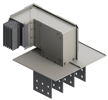
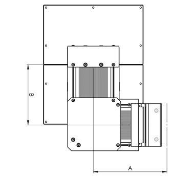
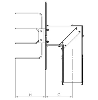
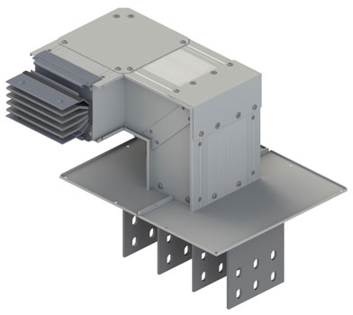
Terminal unit + horizontal elbow
Terminal unit with horizontal elbow.
- HET1 = Terminal unit + horizontal elbow type 1
- HET2 = Terminal unit + horizontal elbow type 2
| STANDARD DIMENSIONS | |||
| A | B | H | |
| B60 | 250 | 180 | 200 |
| B80 | 250 | 180 | 200 |
| B100 | 250 | 180 | 200 |
| B160 | 250 | 180 | 200 |
| B200 | 250 | 180 | 200 |
| B240 | 250 | 180 | 200 |
| 2B160 | 250 | 180 | 200 |
| 2B200 | 250 | 180 | 200 |
| 2B240 | 250 | 180 | 200 |
| MAXIMUM DIMENSIONS | |||
| A | B | H | |
| B60 | 749 | 449 | 200 |
| B80 | 749 | 449 | 200 |
| B100 | 749 | 449 | 200 |
| B160 | 749 | 449 | 200 |
| B200 | 749 | 449 | 200 |
| B240 | 749 | 449 | 200 |
| 2B160 | 749 | 449 | 200 |
| 2B200 | 749 | 449 | 200 |
| 2B240 | 749 | 449 | 200 |
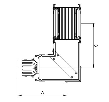
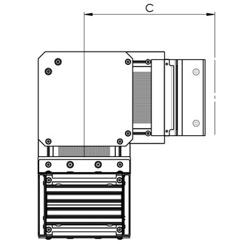
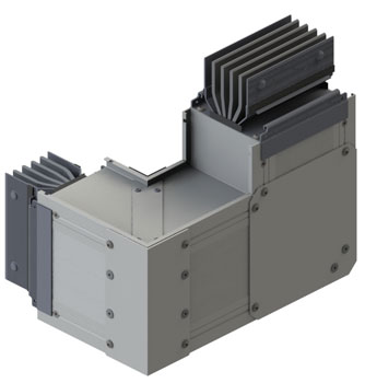
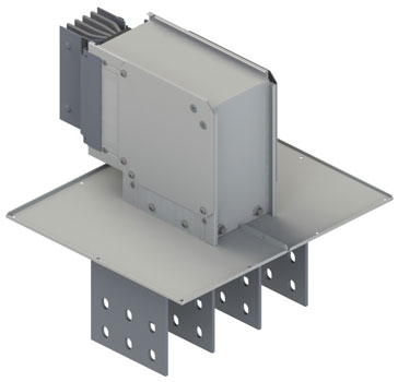
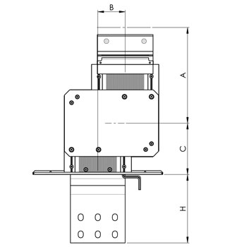
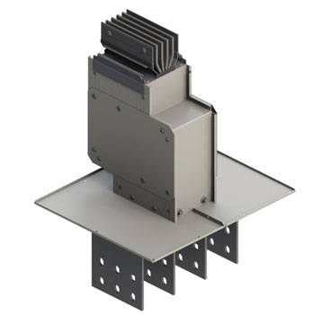
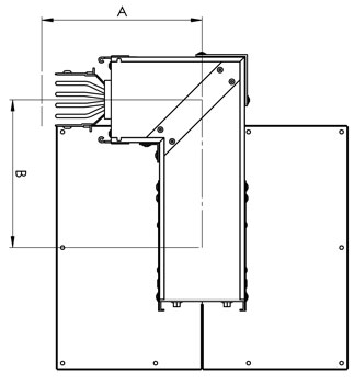
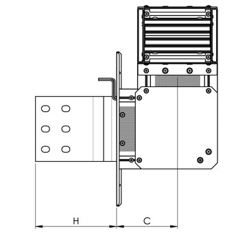
Terminal unit + vertical elbow
Terminal unit with vertical elbow.
- VET1 = Terminal unit + vertical elbow type 1
- VET2 = Terminal unit + vertical elbow type 2
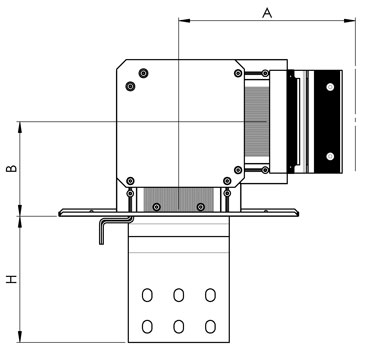
| STANDARD DIMENSIONS | |||
| A | B | H | |
| B60 | 230 | 100 | 200 |
| B80 | 240 | 110 | 200 |
| B100 | 250 | 120 | 200 |
| B160 | 280 | 150 | 200 |
| B200 | 300 | 170 | 200 |
| B240 | 320 | 190 | 200 |
| 2B160 | 370 | 235 | 200 |
| 2B200 | 410 | 275 | 200 |
| 2B240 | 450 | 315 | 200 |
| MAXIMUM DIMENSIONS | |||
| A | B | H | |
| B60 | 729 | 429 | 200 |
| B80 | 739 | 439 | 200 |
| B100 | 749 | 449 | 200 |
| B160 | 779 | 479 | 200 |
| B200 | 799 | 499 | 200 |
| B240 | 819 | 519 | 200 |
| 2B160 | 869 | 569 | 200 |
| 2B200 | 909 | 609 | 200 |
| 2B240 | 949 | 649 | 200 |
Terminal unit + double horizontal elbow
Terminal unit with double horizontal elbow.
- DHT1 = Terminal unit + double horizontal elbow type 1
- DHT2 = Terminal unit + double horizontal elbow type 2
| STANDARD DIMENSIONS | ||||
| A | B | C | H | |
| B60 | 250 | 70 | 180 | 200 |
| B80 | 250 | 70 | 180 | 200 |
| B100 | 250 | 70 | 180 | 200 |
| B160 | 250 | 70 | 180 | 200 |
| B200 | 250 | 70 | 180 | 200 |
| B240 | 250 | 70 | 180 | 200 |
| 2B160 | 250 | 70 | 180 | 200 |
| 2B200 | 250 | 70 | 180 | 200 |
| 2B240 | 250 | 70 | 180 | 200 |
| MAXIMUM DIMENSIONS | ||||
| A | B | C | H | |
| B60 | 749 | 499 | 429 | 200 |
| B80 | 749 | 499 | 429 | 200 |
| B100 | 749 | 499 | 429 | 200 |
| B160 | 749 | 499 | 429 | 200 |
| B200 | 749 | 499 | 429 | 200 |
| B240 | 749 | 499 | 429 | 200 |
| 2B160 | 749 | 499 | 429 | 200 |
| 2B200 | 749 | 499 | 429 | 200 |
| 2B240 | 749 | 499 | 429 | 200 |
Terminal unit + double vertical elbow
Terminal unit with double vertical elbow.
- VET1 = Terminal unit + double vertical elbow type 1
- VET2 = Terminal unit + double vertical elbow type 2
| STANDARD DIMENSIONS | ||||
| A | B | C | H | |
| B60 | 230 | 80 | 100 | 200 |
| B80 | 240 | 80 | 110 | 200 |
| B100 | 250 | 80 | 120 | 200 |
| B160 | 280 | 80 | 150 | 200 |
| B200 | 300 | 80 | 170 | 200 |
| B240 | 320 | 80 | 190 | 200 |
| 2B160 | 370 | 80 | 235 | 200 |
| 2B200 | 410 | 80 | 275 | 200 |
| 2B240 | 450 | 80 | 315 | 200 |
| MAXIMUM DIMENSIONS | ||||
| A | B | C | H | |
| B60 | 729 | 459 | 429 | 200 |
| B80 | 739 | 479 | 439 | 200 |
| B100 | 749 | 499 | 449 | 200 |
| B160 | 779 | 559 | 479 | 200 |
| B200 | 799 | 599 | 499 | 200 |
| B240 | 819 | 639 | 519 | 200 |
| 2B160 | 869 | 739 | 569 | 200 |
| 2B200 | 909 | 819 | 609 | 200 |
| 2B240 | 949 | 899 | 649 | 200 |
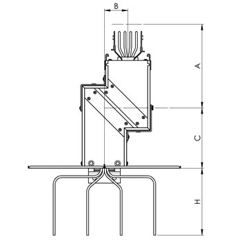
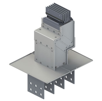
Terminal unit + double elbow vertical + horizontal
Terminal unit with double elbow vertical + horizontal.
- HVT1 = Terminal unit + double elbow vertical + horizontal type 1
- HVT2 = Terminal unit + double elbow vertical + horizontal type 2
- HVT3 = Terminal unit + double elbow vertical + horizontal type 3
- HVT4 = Terminal unit + double elbow vertical + horizontal type 4
| STANDARD DIMENSIONS | ||||
| A | B | C | H | |
| B60 | 250 | 180 | 100 | 200 |
| B80 | 250 | 190 | 110 | 200 |
| B100 | 250 | 200 | 120 | 200 |
| B160 | 250 | 230 | 150 | 200 |
| B200 | 250 | 250 | 170 | 200 |
| B240 | 250 | 270 | 190 | 200 |
| 2B160 | 250 | 315 | 235 | 200 |
| 2B200 | 250 | 355 | 275 | 200 |
| 2B240 | 250 | 395 | 315 | 200 |
| MAXIMUM DIMENSIONS | ||||
| A | B | C | H | |
| B60 | 749 | 479 | 429 | 200 |
| B80 | 749 | 489 | 439 | 200 |
| B100 | 749 | 499 | 449 | 200 |
| B160 | 749 | 429 | 479 | 200 |
| B200 | 749 | 549 | 499 | 200 |
| B240 | 749 | 569 | 519 | 200 |
| 2B160 | 749 | 619 | 569 | 200 |
| 2B200 | 749 | 659 | 609 | 200 |
| 2B240 | 749 | 699 | 649 | 200 |
Terminal unit + double elbow horizontal + vertical
Terminal unit with double elbow horizontal + vertical.
- HVT1 = Terminal unit + double elbow horizontal + vertical type 1
- HVT2 = Terminal unit + double elbow horizontal + vertical type 2
- HVT3 = Terminal unit + double elbow horizontal + vertical type 3
- HVT4 = Terminal unit + double elbow horizontal + vertical type 4
| STANDARD DIMENSIONS | ||||
| A | B | C | H | |
| B60 | 230 | 180 | 180 | 200 |
| B80 | 240 | 190 | 180 | 200 |
| B100 | 250 | 200 | 180 | 200 |
| B160 | 280 | 230 | 180 | 200 |
| B200 | 300 | 250 | 180 | 200 |
| B240 | 320 | 270 | 180 | 200 |
| 2B160 | 370 | 315 | 180 | 200 |
| 2B200 | 410 | 355 | 180 | 200 |
| 2B240 | 450 | 395 | 180 | 200 |
| MAXIMUM DIMENSIONS | ||||
| A | B | C | H | |
| B60 | 729 | 479 | 449 | 200 |
| B80 | 739 | 489 | 449 | 200 |
| B100 | 749 | 499 | 449 | 200 |
| B160 | 779 | 429 | 449 | 200 |
| B200 | 799 | 549 | 449 | 200 |
| B240 | 819 | 569 | 449 | 200 |
| 2B160 | 869 | 619 | 449 | 200 |
| 2B200 | 909 | 659 | 449 | 200 |
| 2B240 | 949 | 699 | 449 | 200 |
End feeder
This unit is used to feed the busbar by cables.
- FED1 = End feeder standard
- FED2 = End feeder special
- FVR1 = End feeder for vertical runs type 1
- FVR2 = End feeder for vertical runs type 2
Terminal unit with parallel phases
This unit is used to prepare the connection between the busbar and cast resin transformer.
- TPP1 = Terminal unit with parallel phase type 1
- TPP2 = Terminal unit with parallel phase type 2
This element will be designed by our engineering according to installation specification.
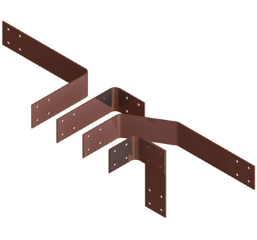
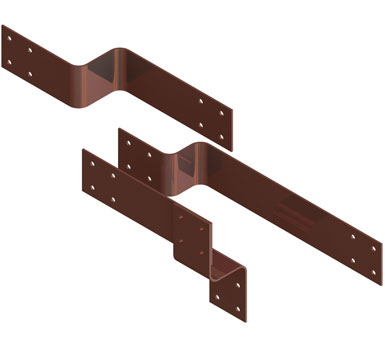
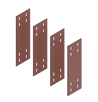
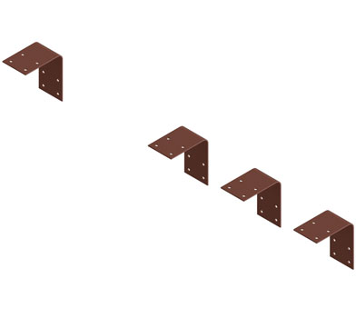
Monoblock, switchgear, end cover, mounting brackets
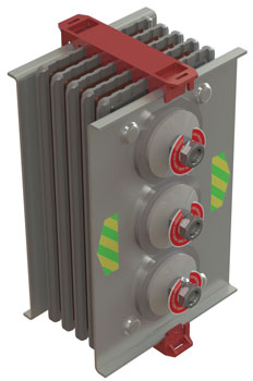
- MON1 = Monoblock
- JCO1 = JOIN COVER
Please assume 1 joint cover and 1 monoblock for each element of the busbar.
- ECO1 = JoinT Cover
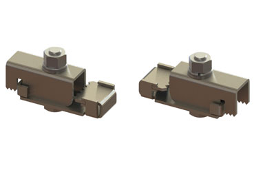
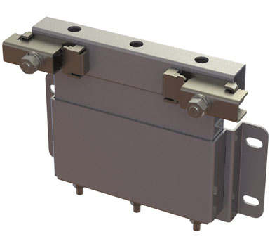
- FIUS = Universal fixing unit
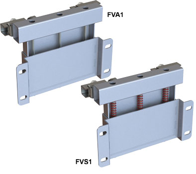
- FVS1 = Fixing unit for vertical runs spring
- FVA1 = Fixing unit for vertical runs
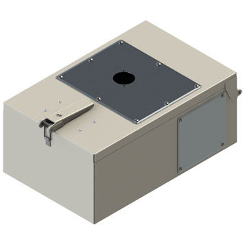
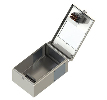
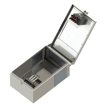
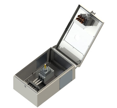
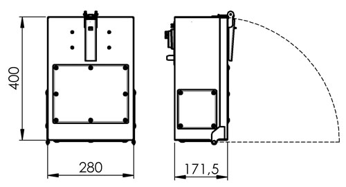
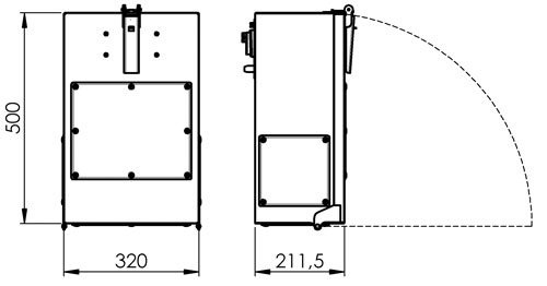
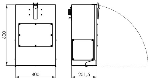
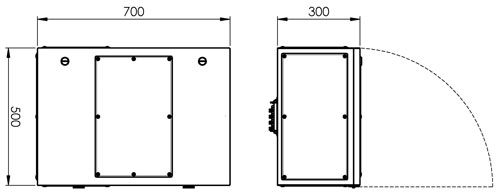
Tap off boxes
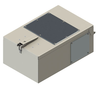
The POWERTECH Tap Off Boxes can be installed on distribution trunking facilities in full safety even with working busbar.
The assembly in a tight space condition is allow thanks to the quick coupling system that allow the easy and fast positioning without the use of bolts or other kind of operations.
- TCE = Empty tap off box 32A-315A
- TCF = Tap off box with fuse holder 32A-315A
- TCD = Tap off box with switch-disconnector and fuse holder 32A-630A
- TCE = Tap off box pre-fitted for MCCB ABB
- TCN = Tap off box pre-fitted for MCCB Schneider
- TCP = Tap off box pre-fitted for MCCB Legrand
- TCL = Tap off box pre-fitted for MCCB Siemens
- TCM = Tap off box pre-fitted for modular switches
Installation instructions
STAGE 1
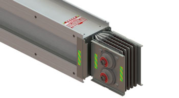
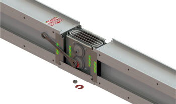
None of the elements of the busbar have the monoblocks mounted. These are deliverde in cardboard boxes to prevent both damage that may occur during transport and educing the risk of the during the storage on site.
STAGE 2
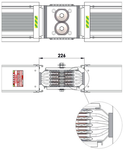
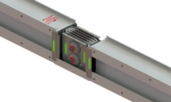
Mount the monoblock on the first element. Correct assembly is facilitated by three factors:
1. The yellow-green symbol is only on one side of the busbar's element and monoblock. The symbols must be located close to each other and on the same side.
2. The presence of visible conducting terminals between monoblock and element which combine in pairs. In case of the improper assembly of the monoblock, the exact match and the parallelism between the plates of monoblock and the earthing conductor.
3. The presence of two plates of diffrent lenght that must match perfectly with the clips placed on the earthing conductors of the element. These two plates are also used to prevent the reversal phases between the two elements that are being mounted.
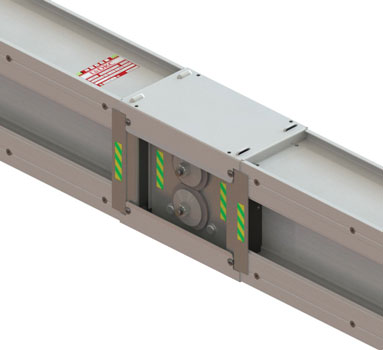
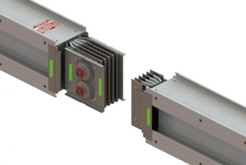
STAGE 3
Place the second element respecting 3 factors described in the previous stage.
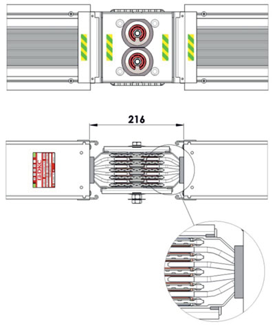
STAGE 4
Please check whether the distance between two elements is 216 mm as shown on the picture. Also check the alignment of the two adjacent elements and two plates of different length that must match perfectly with the clips placed on the earthing conductors of the element.
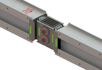
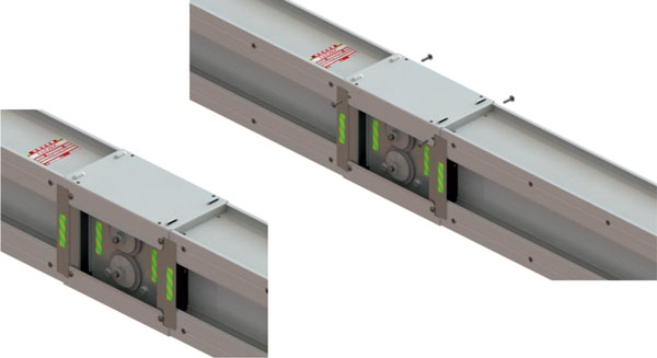
STAGE 5
The verification of the correct position and distance between 2 elements is also checked by placing the conjunction that serves as the cover of the conductive parts.
You cannot mount it if you don't have all conditions described in stage 4.
STAGE 6
STAGE 7
Cartyfikates
POWERTECH™ busbar trunking system is verified in accordance with:
- 10.2.2 Resistance to corrosion
- 10.2.3.2 Resistance to heat and fire due to internal electric effects
- 10.2.5 Listing
- 10.2.6 Mechanical impact
- 10.2.7 Marking
- 10.2.101 Ability to withstand mechanical loads
- 10.3 Degree of protection of assembly
- 10.4 Clearances and creepage distances
- 10.5 Protection against electric shock and integrity of protective circuits
- 10.9 Dielectric properties
- 10.10.2.3.5 Verification of temperaturę-rise limits
- 10.11 Short-circuit withstand strength
- 10.101 Resistance to flame propagation
PN-EN 1366-3/IEC 1366-3
PN-EN 1363-1/IEC 1363-1