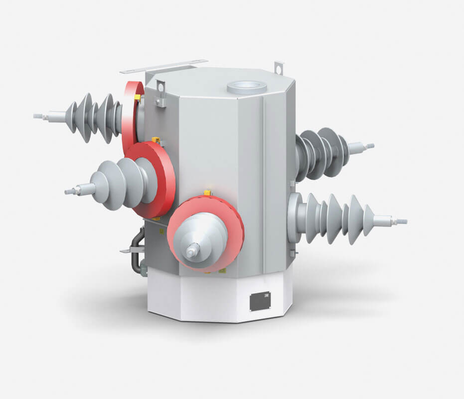
THO-RC27 automatic overhead circuit breaker Recloser consists of the switching unit of the THO-RC27 recloser and control unit SRC. Each switching unit pole has its own vacuum interrupter. All poles are mechanically coupled with a synchronizing shaft which guarantees simultaneous three-phase operation. Vacuum interrupters are opened and closed using a simple electromagnetic actuator with an effective operating lifespan of thirty thousand operations. The electromagnetic drive is actuated by the energy stored in the capacitors. It is composed of one movable part, which differentiates this electromagnetic drive from ordinary spring charged mechanisms. Vacuum interrupters and an electromagnetic drive are placed in completely sealed casing with an IP 65 protection degree.
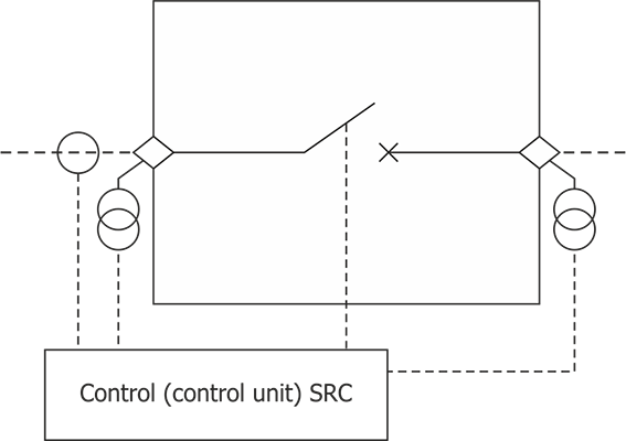
The switching unit can be opened manually using a mechanical rod, actuating manual trip and lock out handle. After being opened manually, the circuit breaker is mechanically and electrically locked out. The circuit breaker position is mechanically indicated with a visual indicator placed at the bottom of the cubicle and electrically with the SRC control unit, which controls the position of the circuit breakers auxiliary contacts. External cover of the bushing insulators is made from water-repellent silicone rubber. Voltage measurement is performed by capacitive voltage dividers installed inside all bushing insulators. Current measurement is performed by installation of the external current transformers 1A secondary current or Rogowski coils on the bushing insulators.
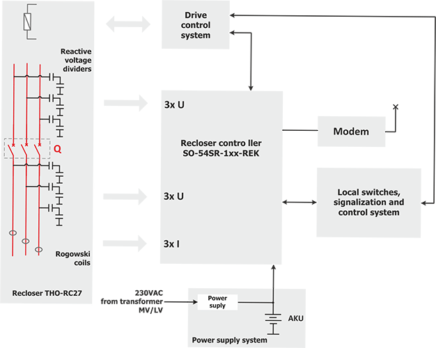
The SRC control unit is designed for complex operation of Recloser THO-RC, incorporating digital protection with a function of SO-54SR- 1xx- REK bay controller and a communication module of any manufacturer, for example: Mikronika MSG- 6xx, Elkomtech EX- BRG, etc., which integrates the following functions: metering, protecting, controlling with a switching unit, telemechanics, automation and multi-channel fault recorder, as well as storing and processing information concerning network parameters and occurring events.
A detailed description of protection and communication modules is included in separate documentation depending on the type of the module used. ZUPE S.A. makes this documentation accessible after an enquiry is made.
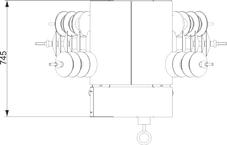
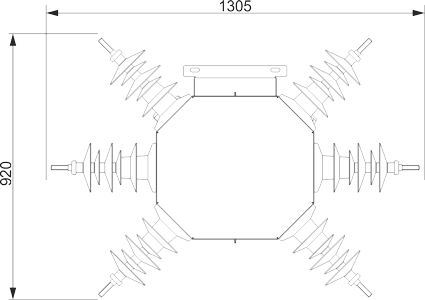
View, dimensions and construction of the switching unit
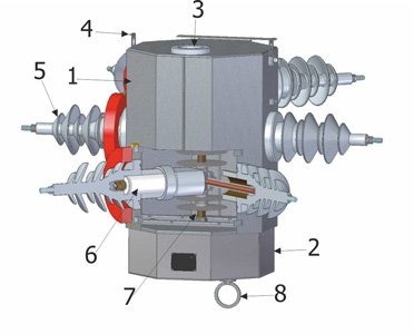
- stainless-steel housing of the recloser
- drive housing, under which is an electromagnetic drive
- safety valve
- lifting brackets
- resin isolator with voltage divider installed inside, covered with silicone rubber
- recloser interrupter installed inside the bushing isolator
- main common shaft for all three poles
- manual open and lock handle
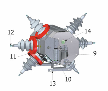
- fast electromagnetic drive
- RX terminal strip
- Rogowski coil or current transformer
- MV cable connection
- lifting bracket for recloser installation on the pole
- visual position indicator
Dimensions and size
Wiew, dimensions and construction of the control unit
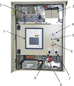
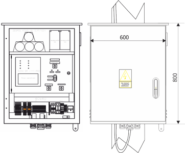
- controller protection SO-54SR-111-REK
- capacitors
- batteries
- operating mode switch: remote, local, reclosing off
- circuit breaker position indication
- local control switches
- live-line operation switch
- automatic reclosing switch (automatic service restoration)
- main protection 230 VAC with an arrester B + C and damage indication