The transmission of reactive power in a power grid system reduces the quality of power grid parameters and increases payments for electricity. The ZPUE S.A. company provides solutions for inductive and capacitive reactive power compensation, such as:
- capacitor banks,
- capacitor banks with protective reactors,,
- inductive banks (to be agreed with the manufacturer, after analysis of electrical grid parameters at the facility).
Reactive power compensation in an electric power system
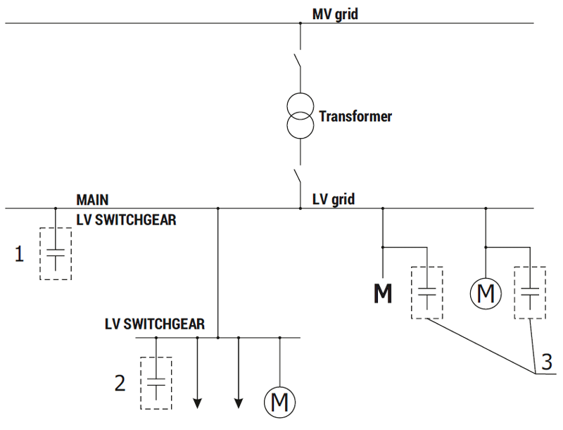
There are three levels of reactive power compensation:
- Central compensation
The bank is installed at the main switchgear (most frequent use). - Group compensation
The bank is installed at the sub-switchgear or near a group of consumers (wide cable grid, distributed consumers). - Individual compensation
Capacitors installed at individual consumers (high power consumers).
| Technical data of the capacitor battery | |
| Rated power | from 40 to 600 kvar 1) |
| Rated power per stage | from 5 to 60 kvar |
| Number of compensation stages | from 4 to 15 |
| Rated operating voltage of the bank | 400 V 2) |
| Rated insulation voltage | 690 V 3) |
| Rated frequency | 50 (60) Hz |
| Busbar rated short-time withstand current | up to 40 kA |
| Ingress protection rating | IP3X 4) |
| Cooperation with current transformers | xx/5 |
| Feeding in power supply cables | from the top or from the bottom |
Note:
1) The banks may be connected into bigger sets.
2) The banks may constructed in 500 V and 690 V versions.
3) In case of 690 V banks the insulation voltage is 750 V.
4) May be constructed up to IP54.
General principles for capacitor bay selection
The share of reactive power in total power consumption is determined by two coefficients. The first is the power coefficient cosφ, which is presented in the relationship (1.1)
![]()
The closer to one cosφ is, the smaller is the share of reactive power. Energy suppliers usually use power factor tgφ in their settlement contracts. A power factor tgφ was received from the relationship (1.2)
![]()
The closer to 0 tgφ is, the smaller is the transmission of reactive power. Based on the obtained tgφ and the demand for active power an approximate capacitor bank power may be obtained. The QBat bank power is established from the relationship (1.3)
![]()
Where tgφ — power factor required by the energy company.
Power and energy diagram
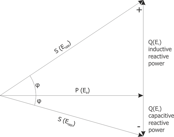
| P - active power [kW] |
| Ea - active energy [kWh] |
| Q - reactive power [kvar] |
| Er - reactive energy [kvarh] |
| S - apparent power [kVA] |
| Eopp - apparent energy [kvah] |
Note!
For the correct selection of a capacitor bank it is necessary to perform electrical grid measurements at the facility.
Protecting the capacitor bank against adverse impact of harmonics.
The use of rectifiers, inverters and frequency converters in state of the art electricity consuming devices often causes deformation of voltage and current, which changes their waveform so that it is no longer a sine wave. They include numerous harmonics, which are an undesirable phenomenon, shortening the lifetime of electrical devices. This phenomenon is particularly dangerous in a capacitor bank. Capacitor reactance decreases when frequency increases, which results in a high intensity current flowing through the capacitor and destroying it. In order to protect the capacitor bank against adverse impact of harmonics, protective reactors connected in series with capacitors are used.
The degree to which distortions are present in the grid (the amount of harmonics) is specified by THD (Total Harmonic Distortion). The type of capacitor bank protection is selected depending on THD value.
| THD ≤ 15% | Capacitor bank with normal capacitors (Un Kond = 400 V) |
| 15% ≤ THD ≤ 25% | Capacitor bank with heavy duty capacitors (Un Kond = 440 V) |
| 25% ≤ THD ≤ 50% | Capacitor banks with compensating reactors |
| THD > 50% | Semiconductor-based tracking compensator |
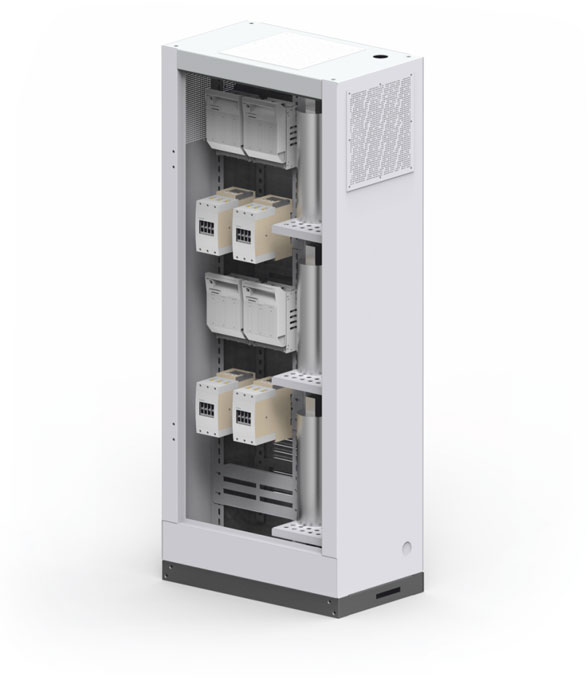
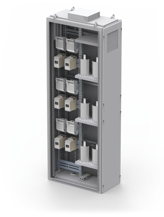
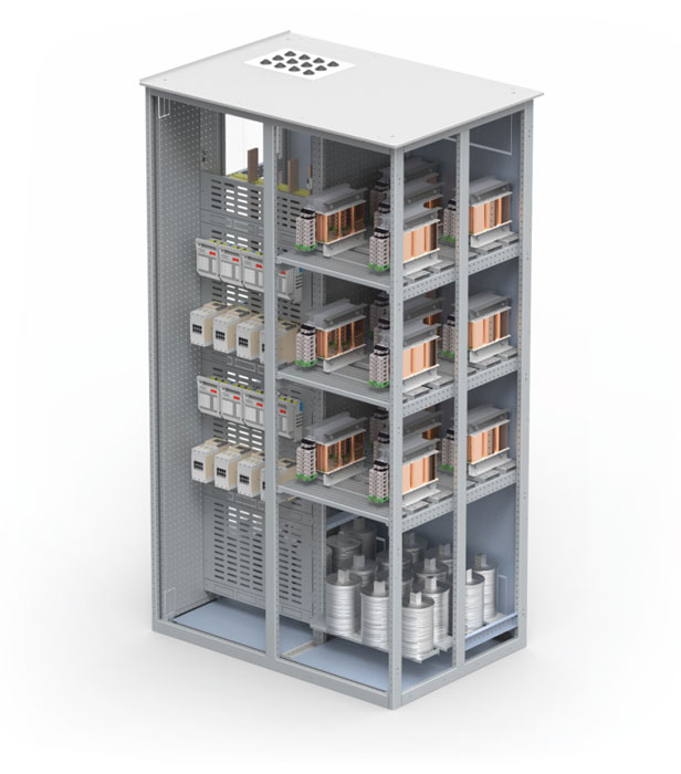
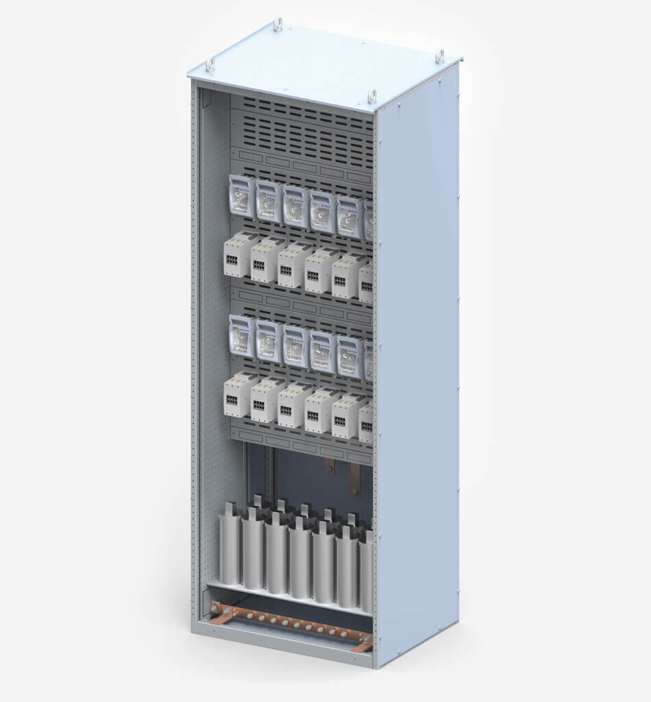
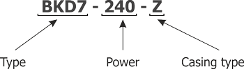
Capacitor banks made by ZPUE S.A. are identified by bank type symbol and enclosure type symbol
| Bank type | |
| BI | Inductive bank |
| BK | Normal capacitor bank (Un Kond = 400V) |
| BKW | Heavy duty capacitor bank (Un Kond = 440V) |
| BKD7 | Capacitor bank with reactors 7% |
| BKD14 | Capacitor bank with reactors 14% |
| Enclosure type | |
| R | RN-W type enclosure |
| I | INSTAL-BLOK type enclosure |
| Z | ZR-W type enclosure |