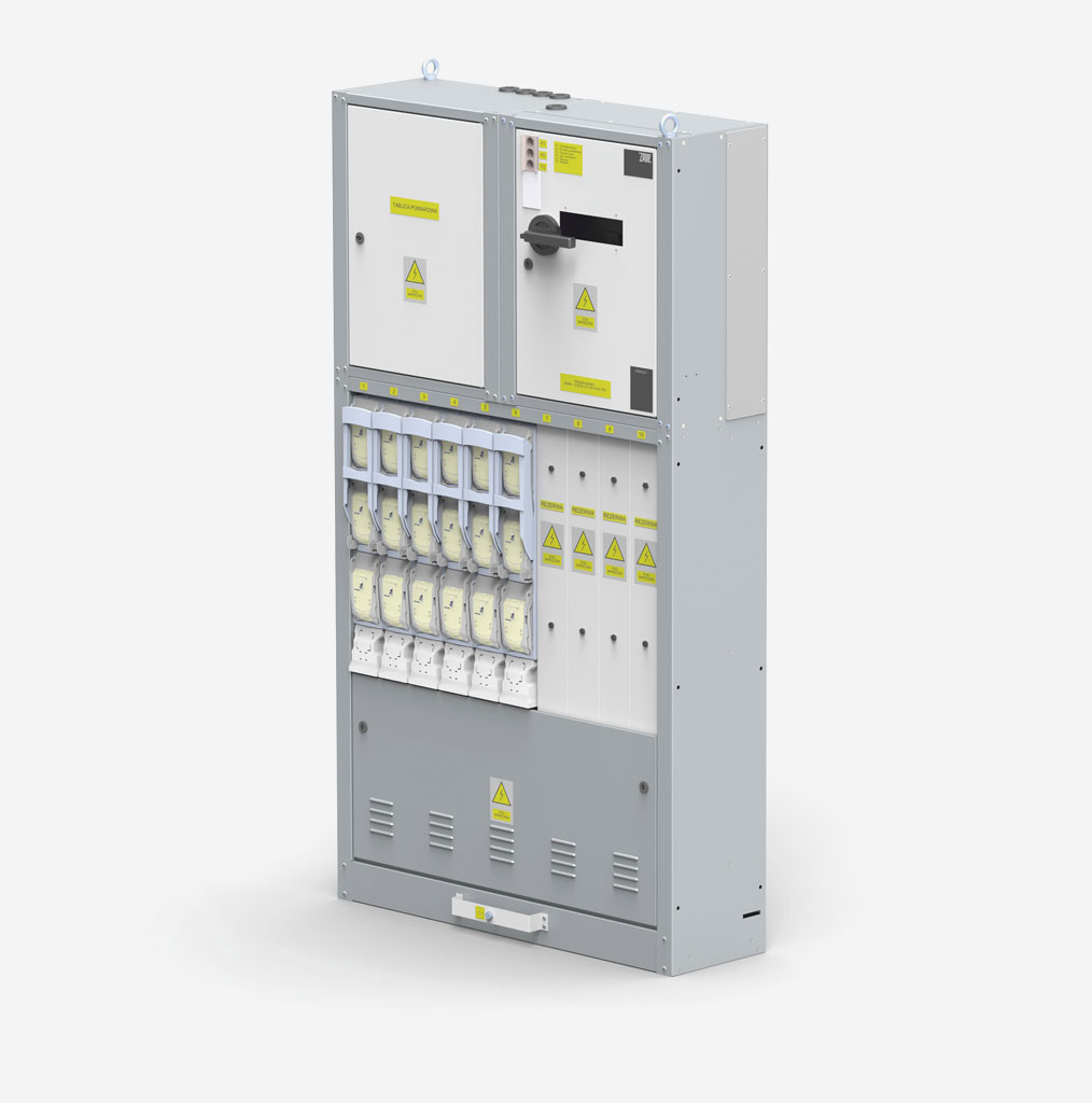
The subject of this page is an RN-W type low voltage switchgear intended to supply LV electrical devices. This type of switchgear is widely used in municipal transformer stations, in industrial plants, department stores and other facilities.
Functional modules of the switchgear
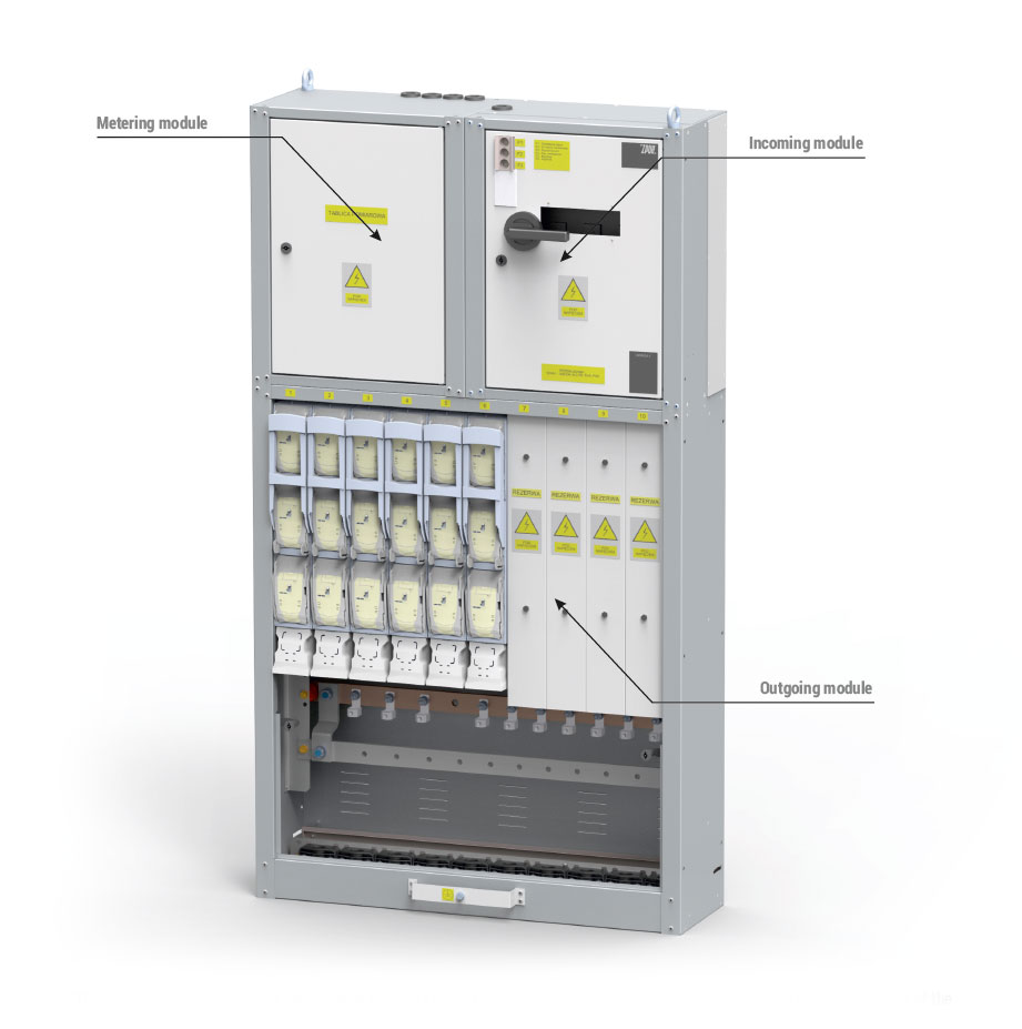
The switchgear is composed of independent elements (modules) which may be assembled into various sets. The basic modules of the RN-W switchgear include:
- outgoing module,
- incoming module,
- metering module,
- other modules, e.g. area lighting, installation devices, automation, etc.
Design options of individual elements are presented in tables.
Outgoing (connection) module
 Between 5 and 12 fuse switch disconnectors of various manufacturers can be installed in the outgoing module, size 1 to 3 with transformers. Outgoing modules can be combined into sets.
| Outgoing module | |||
| Module name | Number of disconnectors for installation from size 1 to 3 (size 00) | Dimensions [mm] [ width x height x depth] | Notes |
| Standard design | |||
| CO-5 | 5 (10) | 550 x 1275 x 400 (320) | For ARS, BTVC and NSL switch disconnectors it is possible to install two size 00 switch disconnectors instead of one size 1 to 3 switch disconnector. |
| CO-10 | 10 (20) | 1100 x 1275 x 400 (320) | |
| Special construction | |||
| CO-6 | 6 (12) | 700 x 1275 x 400 (320) | For ARS, BTVC and NSL switch disconnectors it is possible to install two size 00 switch disconnectors instead of one size 1 to 3 switch disconnector. |
| CO-7 | 7 (14) | 800 x 1275 x 400 (320) | |
| CO-8 | 8 (16) | 900 x 1275 x 400 (320) | |
| CO-9 | 9 (18) | 1000 x 1275 x 400 (320) | |
| CO-12 | 12 (24) | 1300 x 1275 x 400 (320) | |
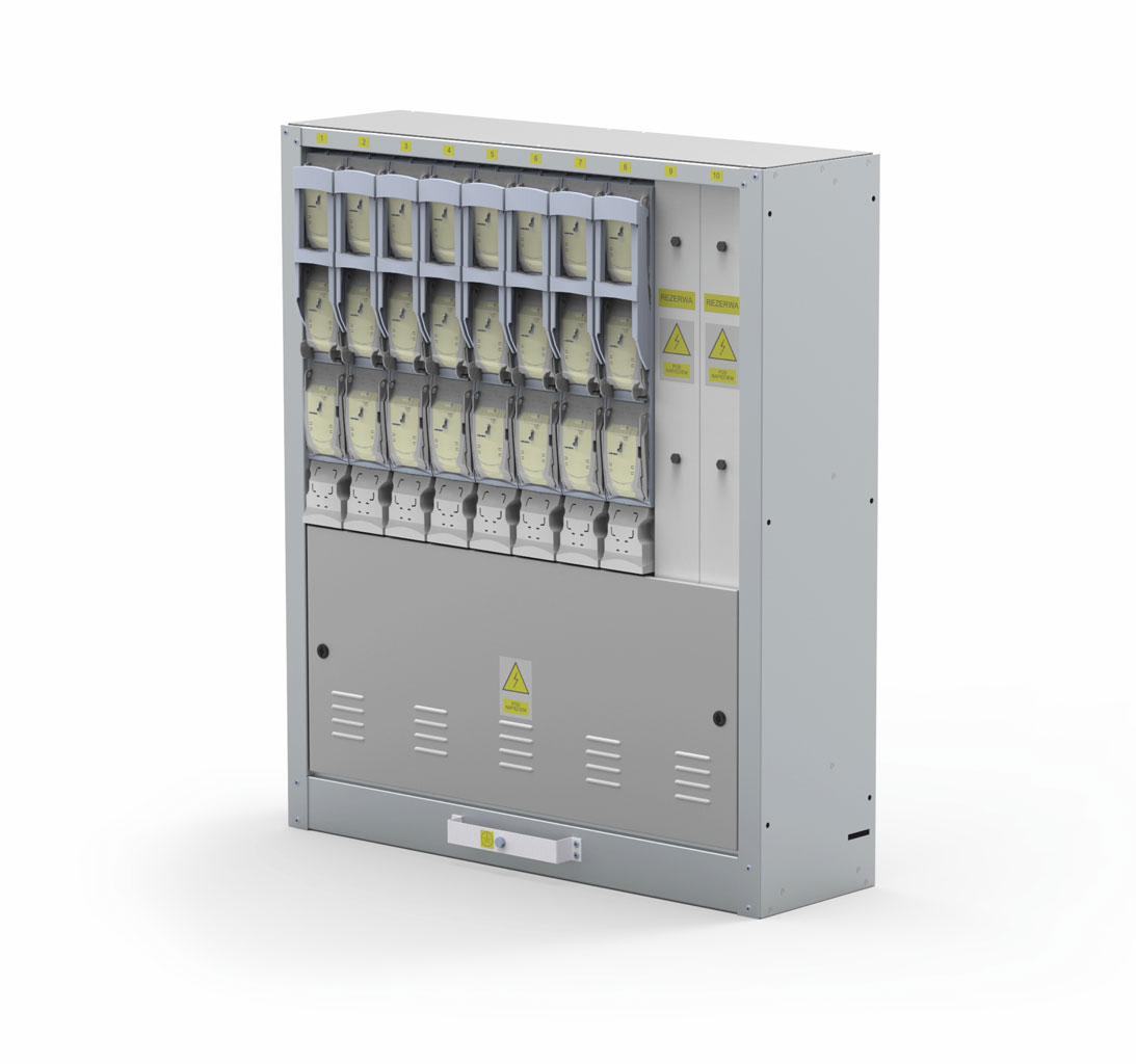
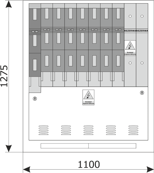
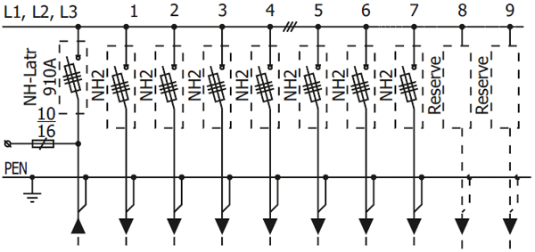
| CZO-1 | 9 (18) | 1100 x 1275 x 400 (320) | The incoming/outgoing module adapted to the installation of an NH – latr 910 type switch disconnector and size 1 to 3 disconnectors. Details, see figure 1. |
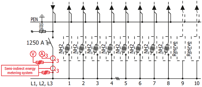
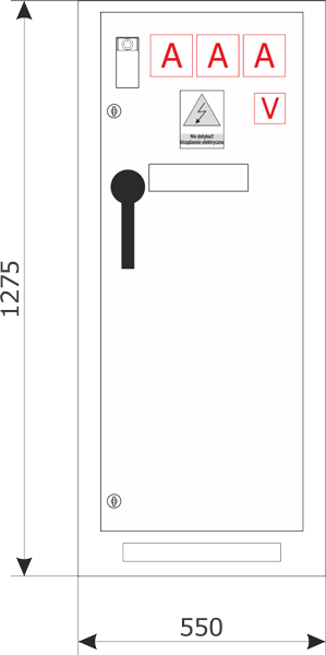
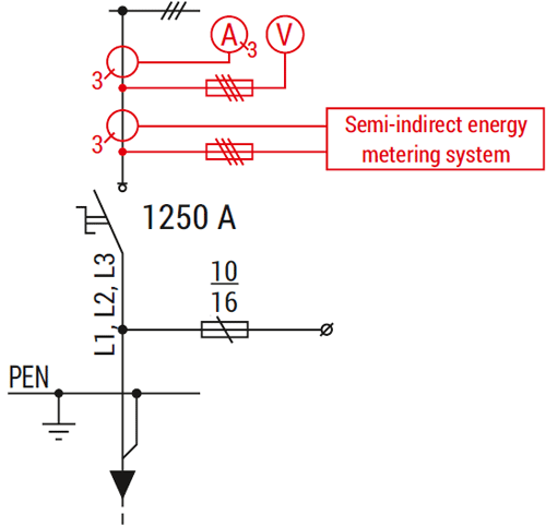
| CZO-2 | 10 (20) | 1650 x 1275 x 400 (320) | The incoming/outgoing module adapted to the installation of an INP-1250 switch disconnector and size 1 to 3 outgoing switch disconnectors. Details, see figure 2. |
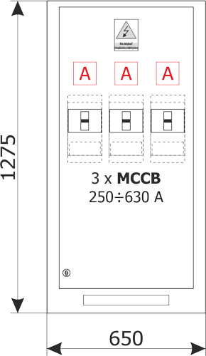
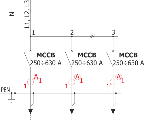
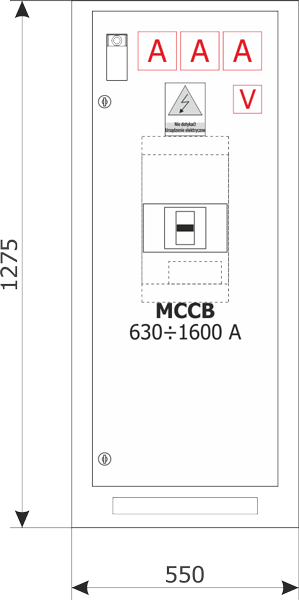
| CO-...XX | 0 | XXX x 1275 x 400 (320) | Outgoing module adapted to the installation of 2 or 3 compact circuit breakers from 250 to 630 A. Details, see figure 3. Module name and dimensions depend on the type and number of installed switch disconnectors. |
Sizes of the used fuse links and cables when cable connections are used. V-klema type depends on the device type:
| Device group | Current ranges of the fuse links | Max. cable cross-section |
| GR. 00 | 6 ÷ 160 A | up to 95 mm2 (depending on the device type) |
| GR. 1 | 6 ÷ 250 A | 240 mm2 (300 mm2 — in case of a wire with a sector cross-section) |
| GR. 2 | 63 ÷ 400 A | |
| GR. 3 | 250 ÷ 630 A |
Examples of custom design:
Additional equipment is marked with red
Additional equipment is marked with red
Incoming compartment (incoming module)
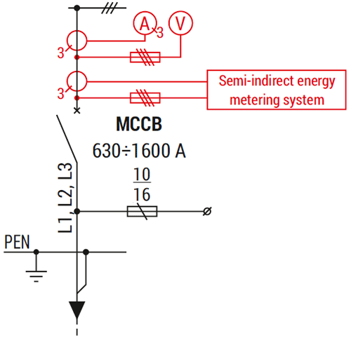
In the incoming module, an INP 1000–2000 switch disconnector or other manufacturer's switch disconnector (after consultation) or compact circuit breaker with rated current (630 – 1600 A) can be installed. The circuit breaker or switch disconnector can be equipped with a motor-drive mechanism. It is also possible to install ammeters, voltmeters or a network analyser.
| Incoming module | |||
| Module name | Installed device | Dimensions [mm] [ width x height x depth] | Notes |
| Standard design | |||
| CZ-1 | INP 1250 or other switch disconnector |
550 x 675 x 400 (320) | The possibility of installation of current transformers, ammeters, voltmeter and transformers for semi-indirect energy metering. |
| Custom design | |||
| CZ-4 | 630–1600 A compact circuit-breaker |
550 x 675 x 400 (320) | Drive on the doors, current transformers may not be installed |
| CZ-5 | 630–1600 A compact circuit-breaker*) |
550 x 800 x 400 (320) | As for standard design |
| CZ-6 | INP 1250 or other switch disconnector*) |
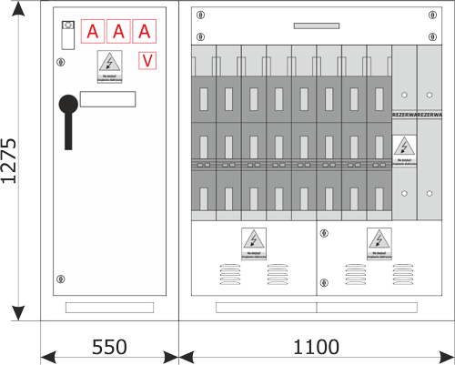
1100 x 1275 x 400 (320) | As for standard design, additionally installation circuit interlocks may be installed for the station's auxiliary circuits. Details, see figure 4. |
| CZ-9 | 630–1600 A compact circuit-breaker*) |
550 x 1275 x 400 (320) | As above. Details, see figure 5. |
*) - the devices used in the switchgear can be equipped with a motor drive, after prior consultation with the manufacturer.
Examples of custom designs:
Additional equipment is marked with red
Additional equipment is marked with red
Metering compartment (metering module)
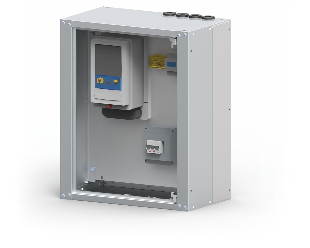
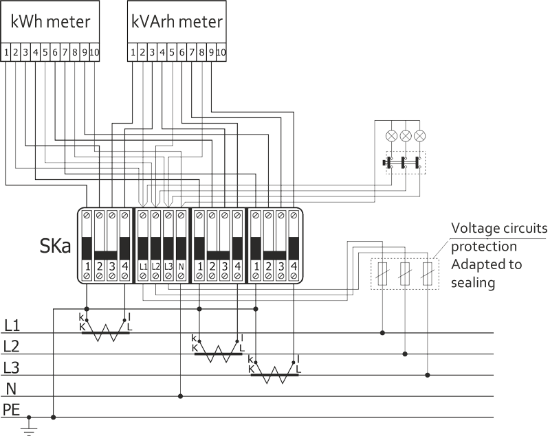
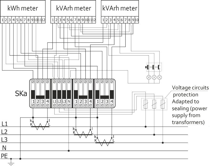
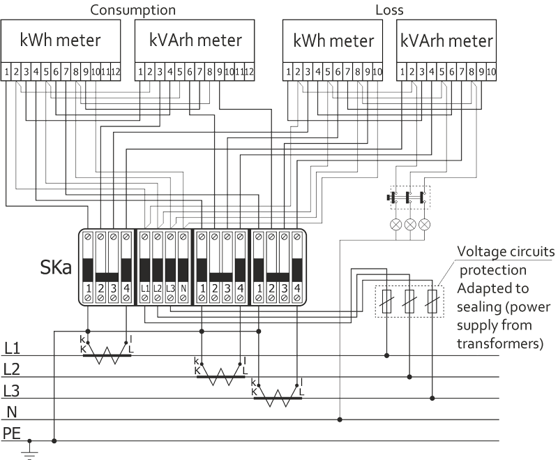
The metering module is used to install an energy meter for billing purposes, designed as a panel for installation of one to four meters. The metering system is also equipped with a metering terminal block, e.g. SKa, and voltage circuits protection.
| Metering module | |||
| Module name | Installed device | Dimensions [mm] [ width x height x depth] | Notes |
| Standard design | |||
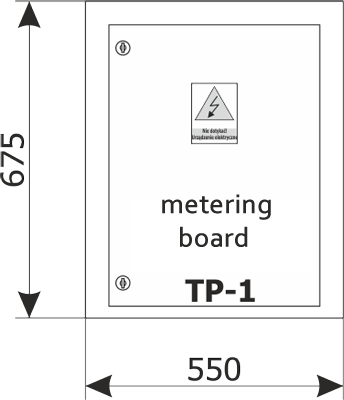
| TP-1 | 1 or 2 electricity meters | 550 x 675 x 400 (320) | Details, see figure 6. |
| Custom design | |||
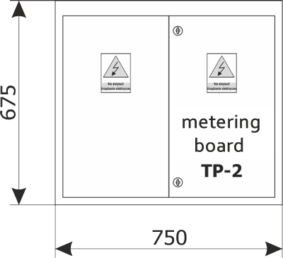
| TP-2 | 3 electricity meters | 750 x 675 x 400 (320) | Details, see figure 7. |
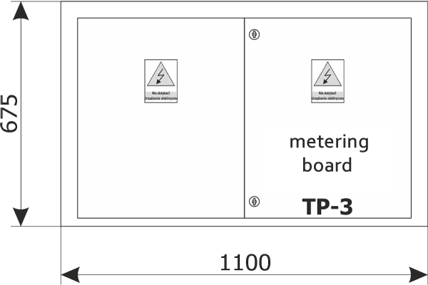
| TP-3 | 3 or 4 electricity meters | 1100 x 675 x 400 (320) | Details, see figure 8. |
Examples of custom design:
Other compartments and additional elements
In the RN-W switchgear other modules may be installed in standard dimension cabinets, e.g.:
- area lighting module,
- installation outgoing feeders module,
- automation module,
- ATS system module,
- Others
| Other modules | |||
| Module name | Equipment | Dimensions [mm] [width x height x depth] |
Notes |
| Standard design | |||
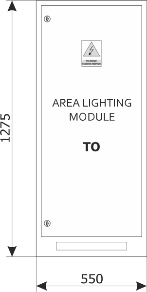
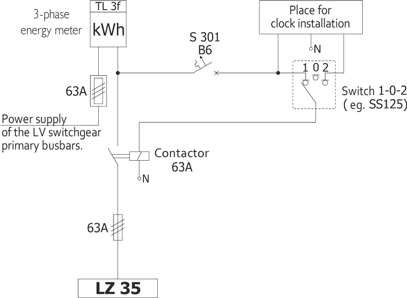
| TO | Area lighting module | 550 x 1275 x 400 (320) | Installed device. Details, see figure 9. |
| Custom design | |||
| TI-1 | Installation switch disconnectors or circuit breaker |
550 x 675 x 400 (320) | 2 rows of modular devices Each row can be equipped with 22 devices with a width of 18 mm |
| TI-2 | Installation switch disconnectors or circuit breaker |
550 x 1275 x 400 (320) | 4 rows of modular devices Each row can be equipped with 22 devices with a width of 18 mm |
| TA-1 TA-2 |
Automation system | 550 x 675 x 400 (320) 550 x 1275 x 400 (320) |
The design of the system to be agreed upon with the manufacturer |
| TSZR | Automatic transfer switching system |
550 x 1275 x 400 (320) | The design of the system to be agreed upon with the manufacturer |
| TX | Other systems | 550 x 675 x 400 (320) 550 x 1275 x 400 (320) |
To be agreed with the manufacturer |
Additional equipment of the RN-W switchgear
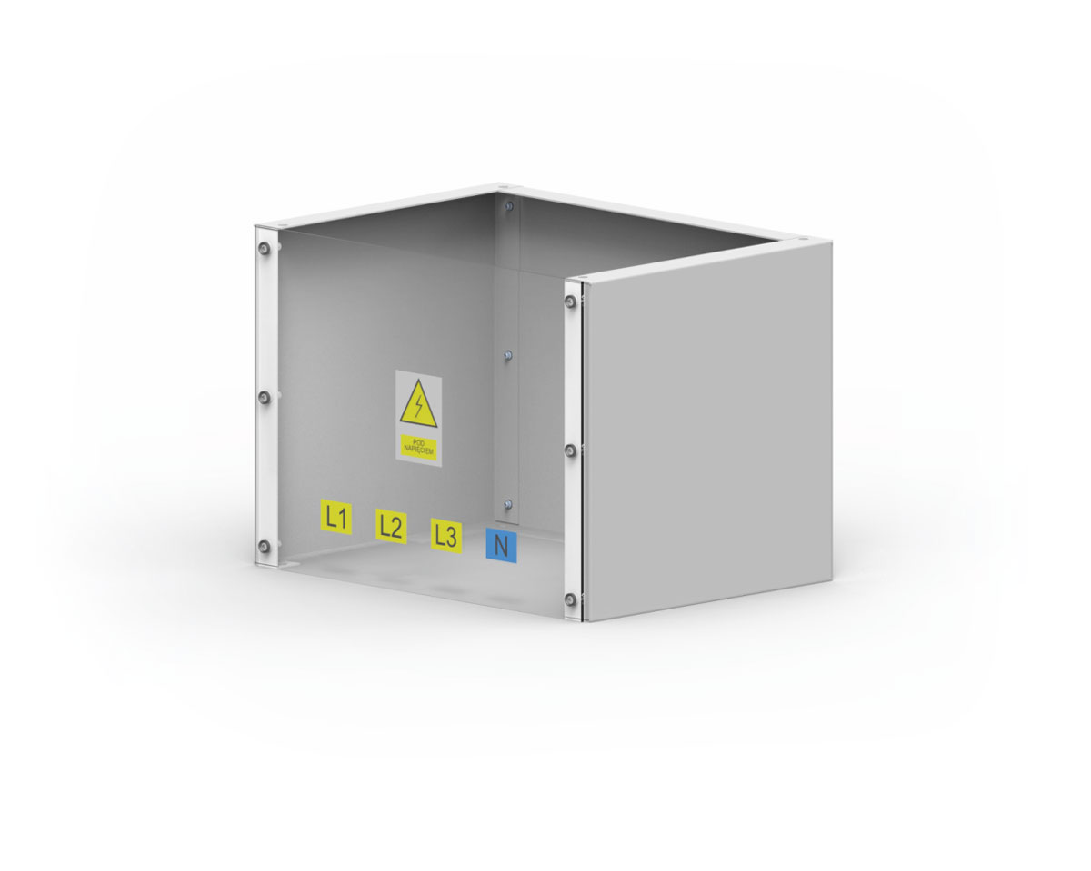
A cover for leading the busbar power supply out of the switchgear. Provides an IP20 protection rating and protects the personnel against touching of live elements.
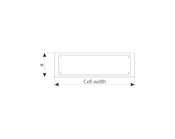
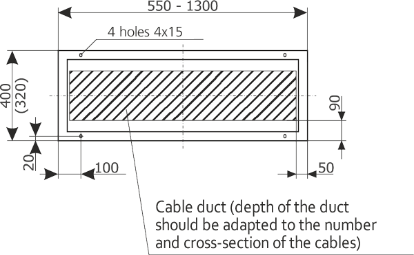
A frame enabling the feeding of cables into the switchgear in rooms without cable trays. The cable frame height “a” depends on the bending radius of the cables.
The RN-W switchgears are designed for indoors installation. They can be placed directly on concrete flooring of the facility. Regardless of the type of foundation, switchgears must be placed exactly horizontally (maximum deviation may not exceed 2mm over 1 m of base length). The switchgear should be fixed to the foundation with 4 M8 bolts in locations shown on figure 11. The power supply is provided at the top of the switchgear with busbars.
NOTE: Busbar connections to the switchgear must be protected from direct contact (using the original cover or one made by the installer), minimum IP20 protection rating.
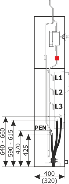
Phase cables are connected directly to devices' terminals. The connection height is shown on figure 12.
The devices are adapted to connection of cables up to 95 mm2 for size 00 devices (depending on the type of device) and to connect cables with a cross-section up to 240 mm2 (300 mm2 conductor with a sector cross-section) for size 1–3 devices.