The ZR-W system switchgears are designed for distribution of electricity at each level, as well as control and protection of electrical devices against short-circuit and overload effects. They can be used as primary switchgears, sub-distribution boards, or as control cabinets.
Their universal configuration enables the use of ZR-W switchgears in the following branches of industry:
- chemical / petrochemical,
- pharmaceutical,
- power plants and CHP plants,,
- heavy industry: mines, steel plants, coking plants,
- light industry: paper, textile, domestic appliances manufacturing.
And in infrastructure:
- data centres,
- airports,
- office buildings,
- shopping centres,
- hospitals.
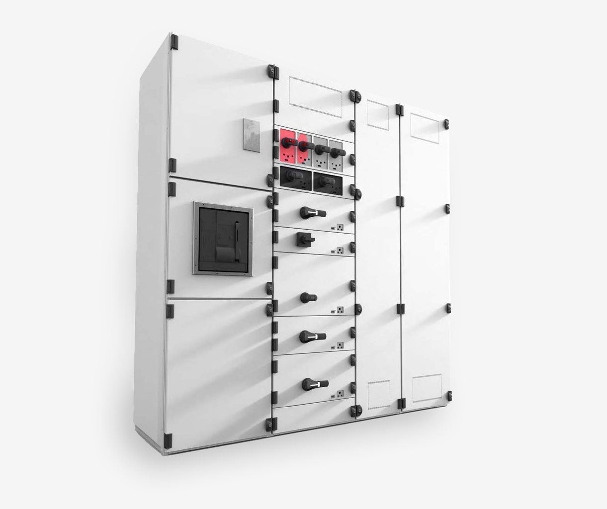
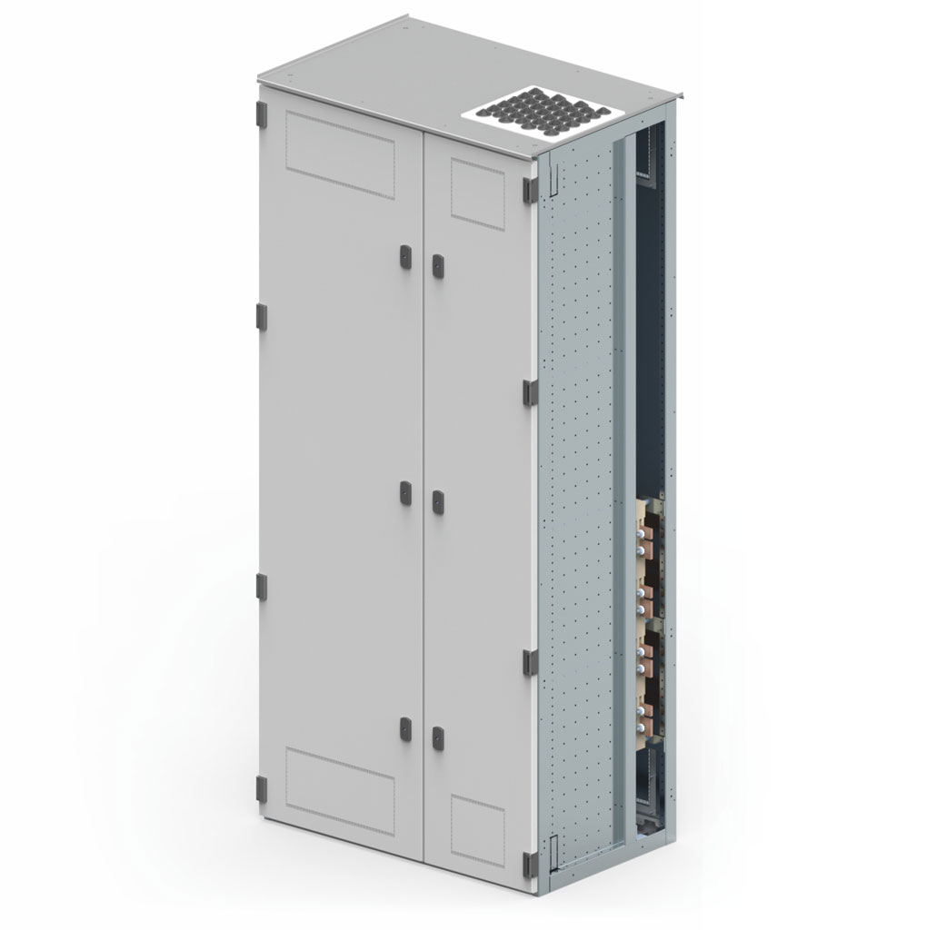
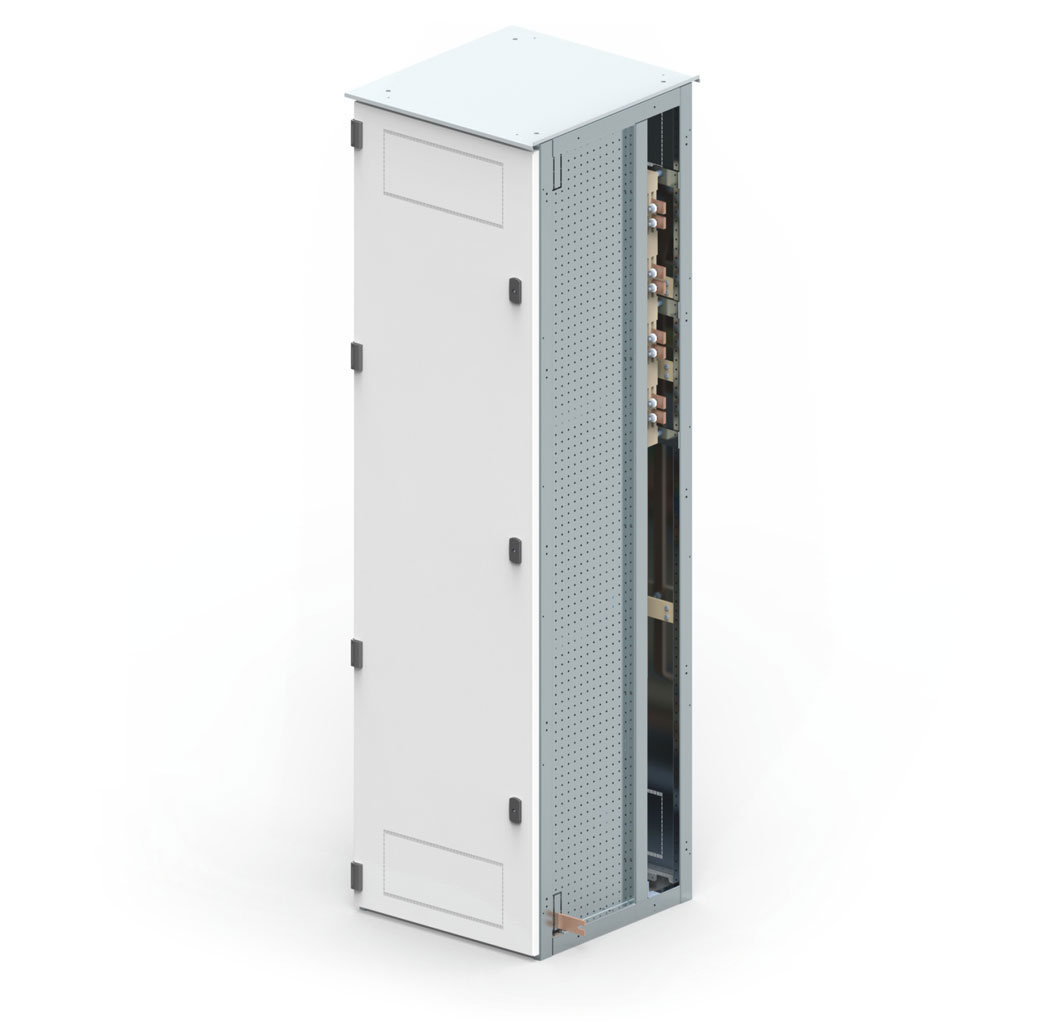
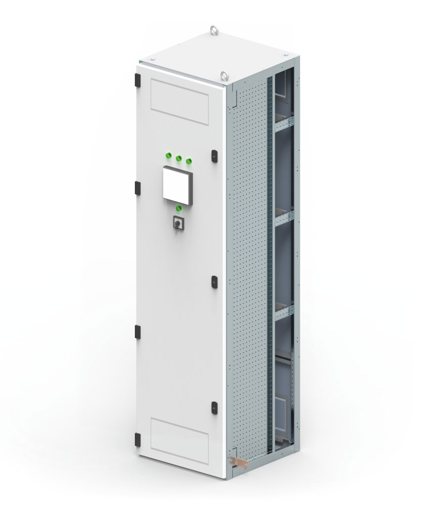
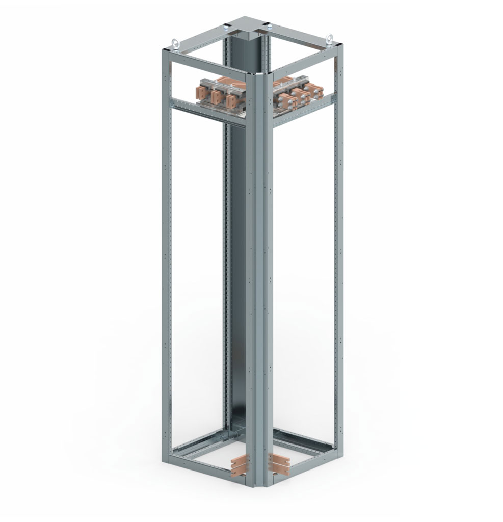
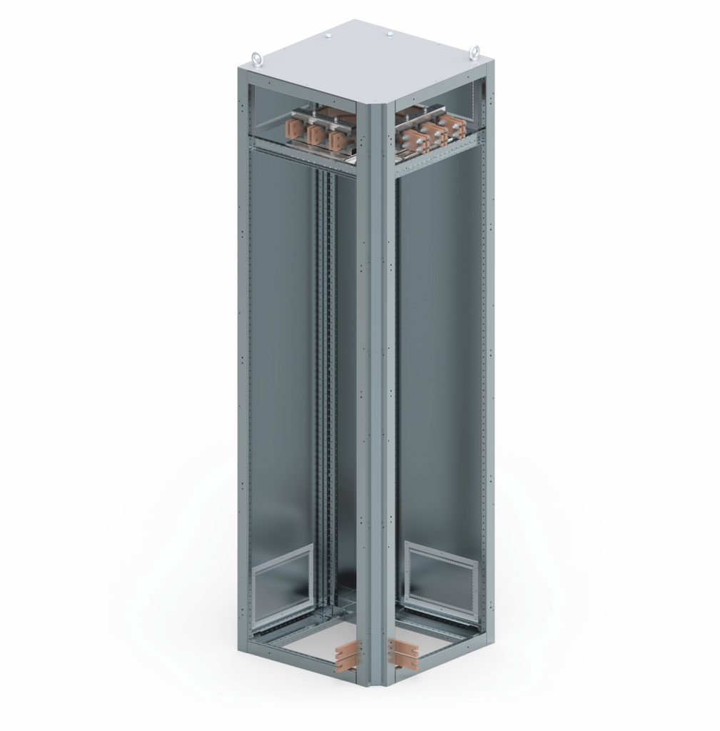
Switchgear design
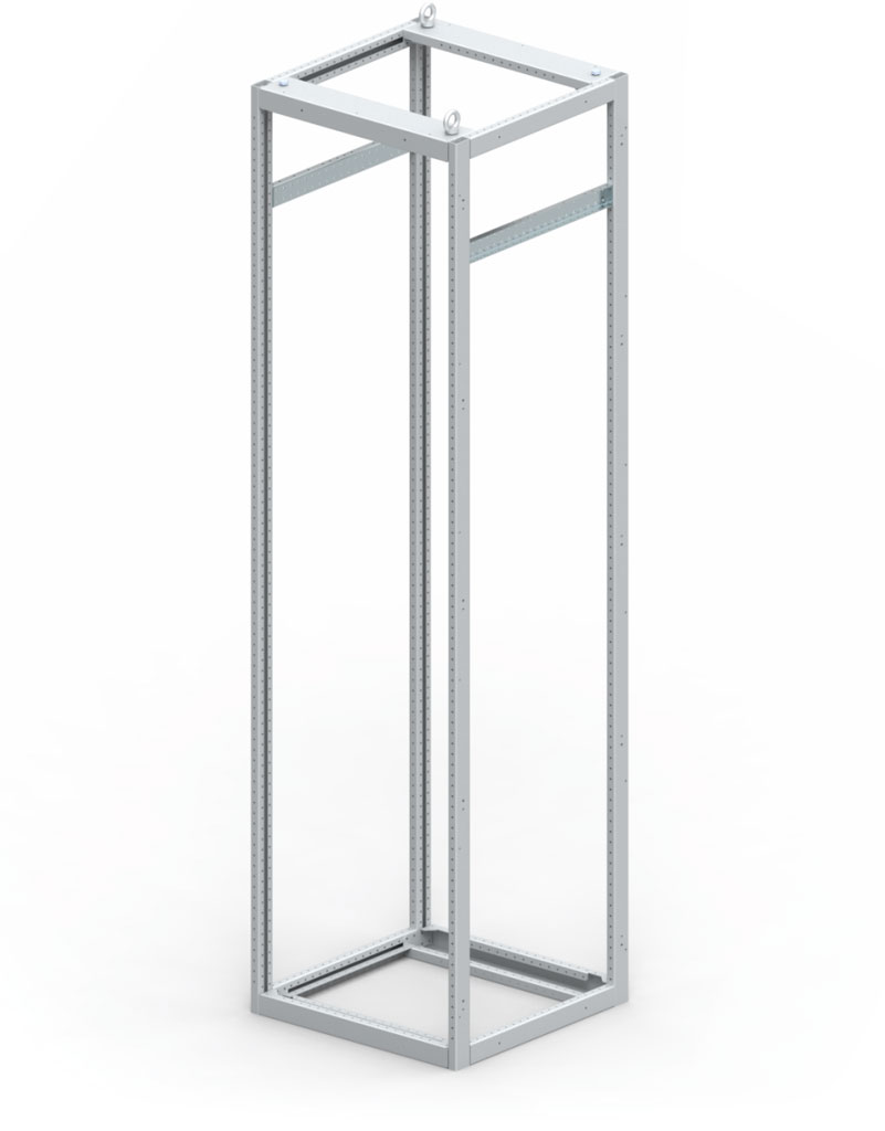
Main mechanical design of the switchgear consists of:
- framework made of zinc-coated profiles,
- functional compartment divider elements, such as vertical and horizontal partitions,
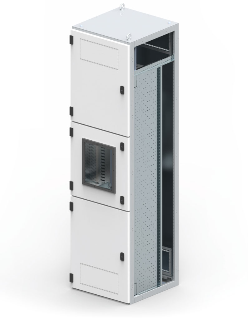
- external covers (doors/side and back walls/roof/floor).
Depending on the method of production, cells can be partially or entirely covered. The door, front covers and back walls can be equipped with ventilation grilles. Inspection windows installed on the door are made from multi-layered glass or plastics.


Bay dimensions
| Construction dimensions | ||
| Height (mm) |
Width (mm) |
Depth (mm) |
| 1900 / 2200 | 400 | 600 / 800 / 1000 |
| 500 | ||
| 600 | ||
| 700 | ||
| 800 | ||
| 900 | ||
| 1000 | ||
| 1100 | ||
| 1200 | ||
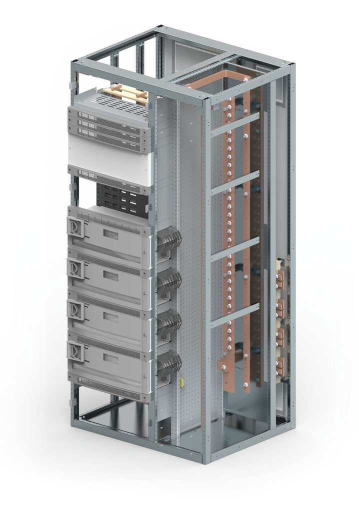
Busbars
Classification of busbars in the ZR-W switchgear according to their function:
- primary busbars,
- distribution busbars,
- protective earth and neutral busbars (PE+N/PEN).
Primary busbars
Primary busbars located at the top of the cabinet
Primary phase busbars and primary neutral N busbars (protective earth-neutral PEN for 4-wire system) are located in the busbar compartment at the top of the switchgear. Primary protective earth PE busbars (for 5-wire system) are located in the front in the lower part of the cabinet along its face.
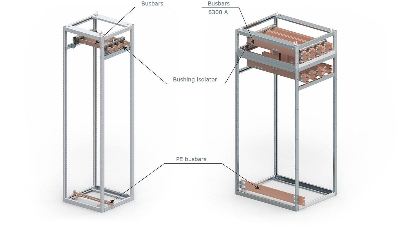

Primary busbars located at the rear of the cabinet
Primary phase busbars and primary neutral N busbars (protective earth-neutral PEN for 4-wire system) are located in the busbar compartment at the rear of the switchgear.
Depending on the configuration, they are placed in its bottom or its top part. Primary protective earth PE busbars (for 5-wire system) are located in the front in the lower part of the cabinet along its face.
Distribution busbars
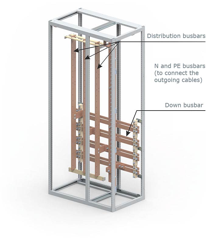
Vertical distribution busbars are located in the busbar compartment, on the left side of the switchgear cabinet. They are used for connecting fixed, plug-in and withdrawable outgoing units. A neutral N busbar and protective earth PE busbar (for 5-wire cable system) or a protective earth neutral PEN (for 4-wire cable system) are then arranged vertically in the connection compartment.
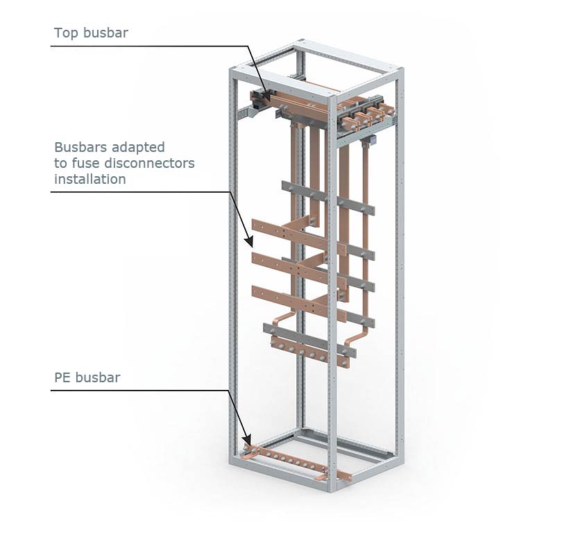
Busbars adapted to strip-type fuse switch disconnectors installation
Busbars located at the front of the switchgear cabinet are used for direct installation of strip-type fuse switch disconnectors.
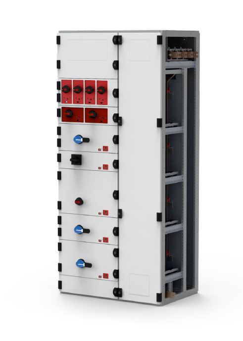
Types of bays
The ZR-W type switchgear is composed of a combination of 9 bay types:
- Circuit breaker bay,
- Bus coupler bay,
- Bay with vertical fuse switch disconnectors,
- Bay with horizontal fuse switch disconnectors,
- Outgoing bay,
- Free installation bay,
- MCC type cassette bay,
- Capacitor bank bay,
- Corner bay.
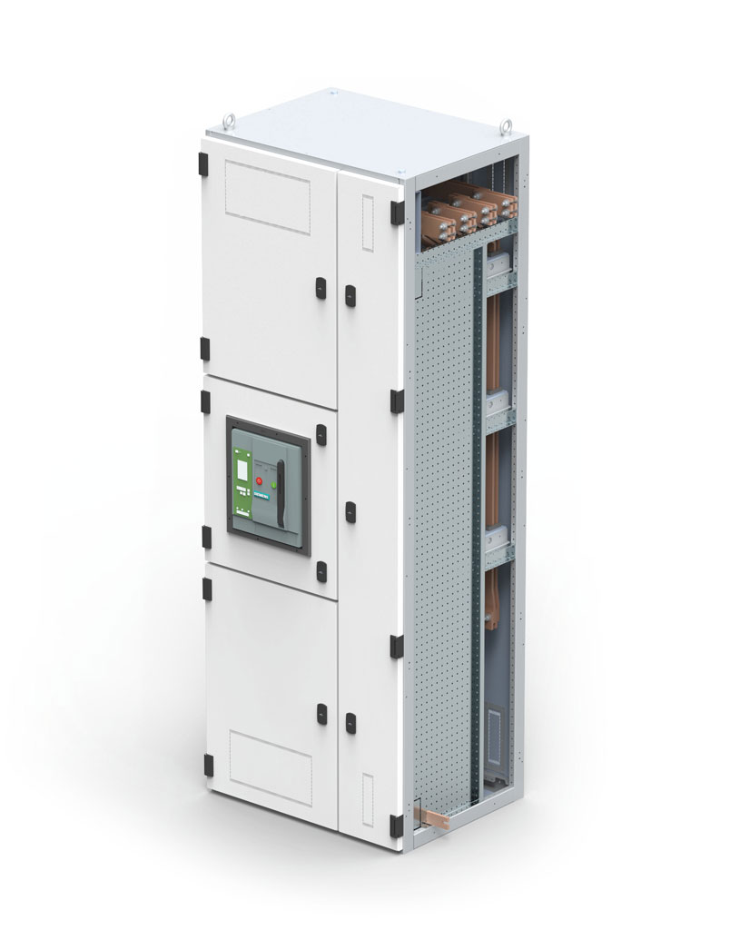
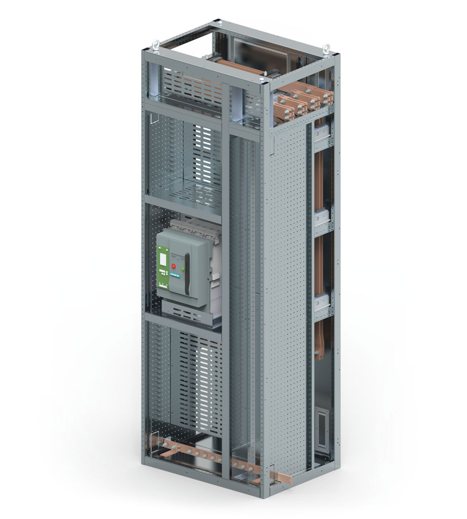
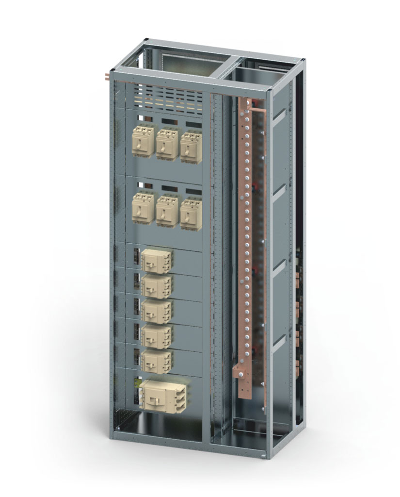
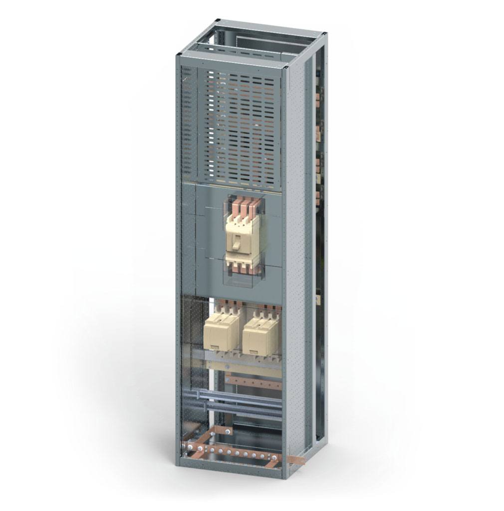
Circuit breaker bay
| Technical data of the circuit breaker bay | ||
| Area of application |
Incoming feeder |
|
| Ingress protection rating | Ventilated up to IP41 Non-ventilated up to IP54 |
|
| Bay dimensions | Height Width Depth |
1900 / 2200 mm 400*) / 500 / 600 / 700 / 800 / 900/ 1000 / 1100 / 1200 mm 600 / 800 / 1000 mm |
| Possibility of installing devices | Air circuit breaker up to 6300 A Compact circuit breaker up to 1600 A |
|
| Form of compartments | Form 2B / 3A / 4B | |
| Bay construction method | ||
| Primary busbars placed at the top |
Bay depth 600 | Connection: - busbar: side / rear / bottom - bus duct: bottomm - cable: bottom, up to 12 cables of 240 mm2 |
| Primary busbars placed at the top |
Bay depth 800 / 1000 | Connection: - busbar: side / rear / bottom - bus duct: bottom - cable: top, up to 12 cables of 240 mm2 |
| Primary busbars placed at the back |
Bay depth 600 | Connection: - busbar: side / bottom - bus duct: bottom - cable: top, up to 12 cables of 240 mm2 |
| Primary busbars placed at the back |
Bay depth 800 / 1000 | Connection: - busbar: side / top / bottom - bus duct: bottom - cable: top, up to 12 cables of 240 mm2 |
*) Solution only for bays with busbars at the back.
| Minimum bay dimensions depending on the installed devices | ||||
| Device type | Rated current | Bay width (3-pole devices) |
Bay width Device type (4-pole devices) |
Bay depth |
| Fixed or withdrawable compact circuit breaker |
Up to 1600 A | 400*) / 500 mm | 600 mm | 600 mm |
| Fixed or withdrawable power circuit breaker |
Up to 1600 A | 600 mm | 800 mm | 600 mm |
| Stationary compact circuit breaker | From 2000 to 3200 A | 600*) / 700 mm | 800 mm | 600 mm |
| Withdrawable compact circuit breaker | From 2000 to 2500 A | 600*) / 700 mm | 800 mm | 600 mm |
| Stationary compact circuit breaker | 4000 A | 800 mm | 900 mm | 800 mm |
| Withdrawable compact circuit breaker | From 3200 to 4000 A | 800 mm | 900 mm | 800 mm |
| Fixed or withdrawable power circuit breaker |
From 5000 to 6300 A | 1000 mm | 1200 mm | 1000 mm |
*) Solution only for bays with busbars at the back.
Bus coupler bay
| Technical data of the bus coupler bay | ||
| Area of application | Coupler between sections | |
| Ingress protection rating | Ventilated up to IP41 Non-ventilated up to IP54 |
|
| Bay dimensions | Height Width Depth |
1900 / 2200 mm 600*) / 700*) / 800 / 900 / 1000 / 1100 / 1200 mm 600 / 800 / 1000 mm |
| Possibility of installing devices |
Air circuit breaker up to 6300 A Compact circuit breaker up to 1600 A |
|
| Form of compartments | Form 2B / 3A / 4B | |
| Bay construction method | ||
| Primary busbars placed at the top |
Bay depth depends on the incoming bay depth |
Busbar connection of two upper circuits using a riser compartment |
| Primary busbars placed at the back |
Bay depth depends on the incoming bay depth |
Connection of the upper busbar circuit with the bottom busbar circuit |
*) Solution only for bays with busbars at the back.
| Minimum bay dimensions depending on the installed devices | ||||
| Device type | Rated current | Bay width (3-pole devices) |
Bay width (4-pole devices) |
Bay depth |
| Fixed or withdrawable compact circuit breaker |
Up to 1600 A | 600 mm | 700 mm | 600 mm |
| Fixed or withdrawable power circuit breaker |
Up to 1600 A | 700*) / 800 mm | 800 mm | 600 mm |
| Stationary power circuit breaker | From 2000 to 3200 A | 900 mm | 1000 mm | 600 mm |
| Withdrawable power circuit breaker | From 2000 to 2500 A | 900 mm | 1000 mm | 600 mm |
| Stationary power circuit breaker | 4000 A | 1100 mm | 1200 mm | 800 mm |
| Withdrawable power circuit breaker | From 3200 to 4000 A | 1100 mm | 1200 mm | 800 mm |
| Fixed or withdrawable power circuit breaker |
From 5000 to 6300 A | 1200 mm | ------------ | 1000 mm |
*) Solution only for bays with busbars at the back.
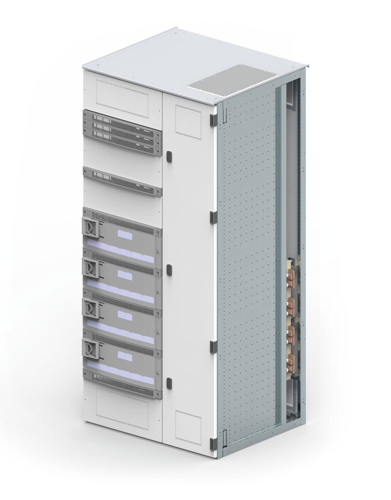
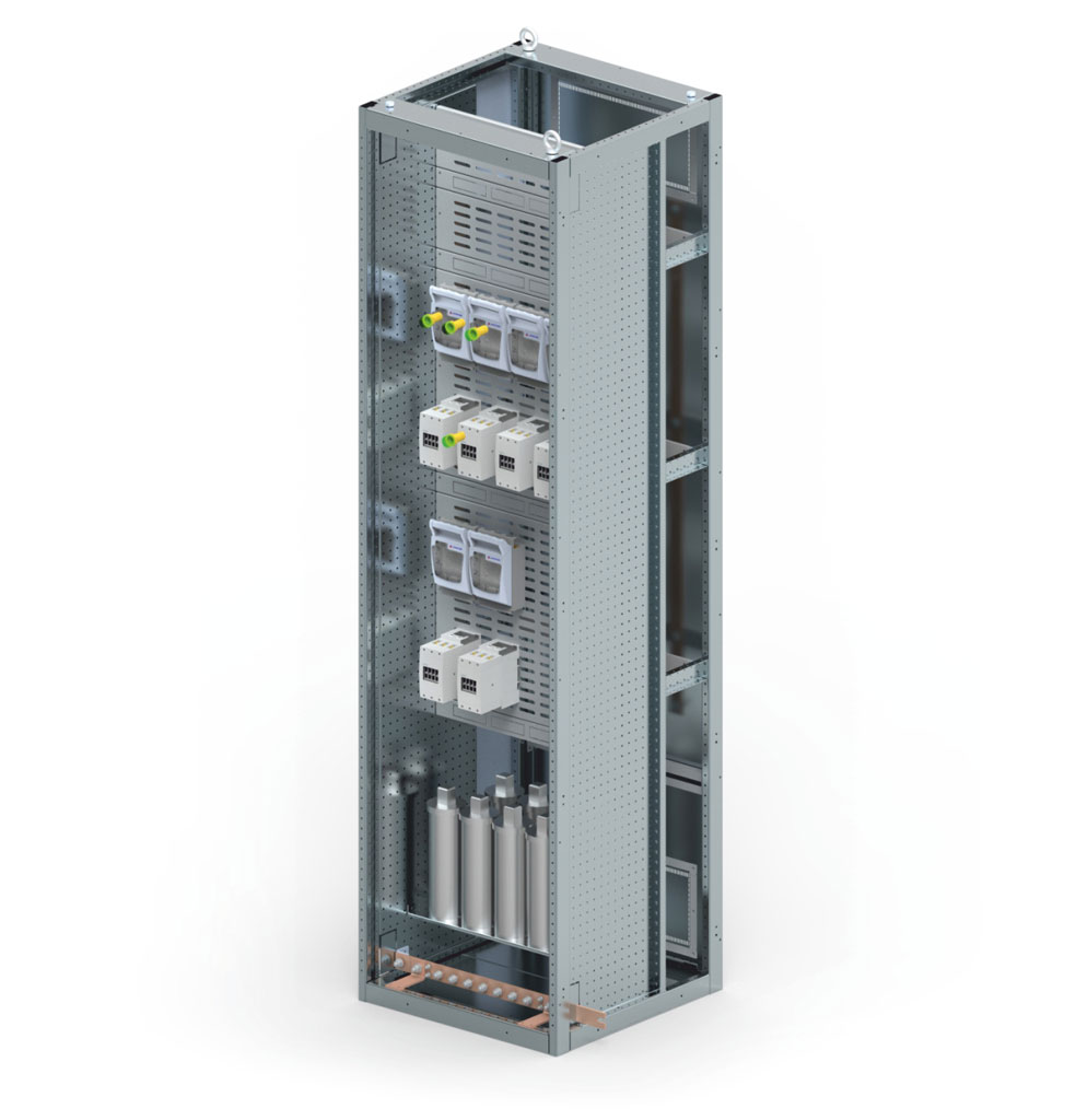
Bay with vertical fuse switch disconnectors
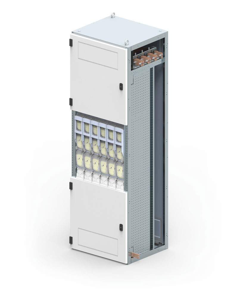
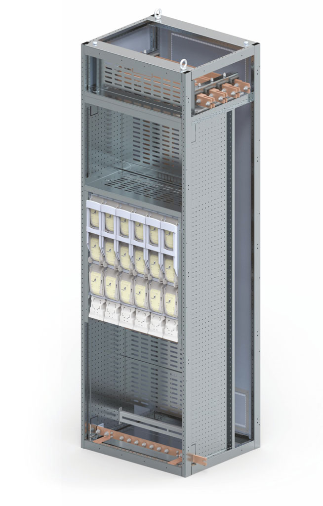
| Technical data of the bay with vertical fuse switch disconnectors: | ||
| Area of application | Outgoing on fuse switch disconnectors | |
| Protection rating | Ventilated up to IP2X Non-ventilated up to IP54 |
|
| Bay dimensions | Height Width Depth |
1900 / 2200 mm 400*) / 500 / 600 / 700 / 800 / 900/ 1000 / 1100 / 1200 mm 600 / 800 / 1000 mm |
| Possibility of installing devices |
Strip-type fuse switch disconnectors, size 00 up to 3 Twin switch disconnector installation (size 3) 800 A / 1000 A / 1250 A |
|
| Form of compartments | Form 2B | |
| Bay construction method | ||
| Primary busbars placed at the top | Bay depth 600 | Connection: - cables from the bottom, up to 3 cables to each switch disconnector, cable cross-sections according to the manufacturer's catalogue |
| Primary busbars placed at the back | Bay depth 600 | Connection: - cables from the bottom or top, up to 3 cables to each switch disconnector, cable cross-sections according to the manufacturer's catalogue |
| Every placement of primary busbars | Bay depth 800 / 1000 | Connection: - cables from the bottom or top, up to 3 cables to each switch disconnector, cable cross-sections according to the manufacturer's catalogue |
*) Solution only for bays with busbars at the back.
| Minimum bay dimensions depending on the installed devices: | |||||||||
| Bay width | 400*) | 500 | 600 | 700 | 800 | 900 | 1000 | 1100 | 1200 |
| Number of 00 size devices | 6 | 8 | 10 | 12 | 14 | 16 | 18 | 20 | 22 |
| Number of 1 size devices | 3 | 4 | 5 | 6 | 7 | 8 | 9 | 10 | 11 |
| Number of 2 size devices | 3 | 4 | 5 | 6 | 7 | 8 | 9 | 10 | ---- |
| Number of 3 size devices | 3 | 4 | 5 | 6 | 7 | ---- | ---- | ---- | ---- |
*) Minimum bay dimensions depending on the installed devices.
Bay with horizontal fuse switch disconnectors
| Technical data of the bay with vertical fuse switch disconnectors: | ||
| Area of application | Outgoing on fuse switch disconnectors | |
| Ingress protection rating | Ventilated up to IP2X Non-ventilated up to Ip54 |
|
| Bay dimensions | Height Width Depth |
1900 / 2200 mm 1100 / 1200 mm 600 / 800 / 1000 mm |
| Possibility of installing devices |
Strip-type fuse switch disconnectors, size 00 up to 3 | |
| Form of compartments | Form 2B / 3B / 4B | |
| Bay construction method | ||
| Primary busbars placed at the top | Bay depth 600 | Connection: - cables from the bottom, up to 3 cables to each switch disconnector, cable cross-sections according to the manufacturer's catalogue |
| Primary busbars placed at the back | Bay depth 600 | Connection: - cables from the bottom or top, up to 3 cables to each switch disconnector, cable cross-sections according to the manufacturer's catalogue |
| Every placement of primary busbars | Bay depth 800 / 1000 | Connection: - cables from the bottom or top, up to 3 cables to each switch disconnector, cable cross-sections according to the manufacturer's catalogue |
| Minimum bay dimensions depending on the installed devices: | ||
| Bay width | 1000 mm | 1200 mm |
| Number of 00 size devices | up to 15 | up to 19 |
| Number of 1 size devices | up to 10 | up to 15 |
| Number of 2 size devices | up to 9 | up to 11 |
| Number of 3 size devices | up to 6 | up to 7 |
Outgoing bay
| Technical data of the outgoing bay: | ||
| Area of application | Outgoings on box fuse switch disconnectors, compact circuit breakers or motor modules |
|
| Protection rating | Ventilated up to IP2X Non-ventilated up to IP54 |
|
| Bay dimensions | Height Width Depth |
1900 / 2200 mm 1000 / 1200 mm 600 / 800 / 1000 mm |
| Possibility of installing devices |
Box fuse switch disconnectors Compact circuit breakers up to 800 A Motor power supply systems (protection/contactor) Modular device |
|
| Form of compartments | Form 2B / 3B / 4B | |
| Bay construction method | ||
| Primary busbars placed at the top | Bay depth 600 | Connection: - cables from the bottom, up to 2 cables to each device, cable cross-sections according to the manufacturer's catalogue |
| Primary busbars placed at the back | Bay depth 600 | Connection: - cables from the bottom or top, up to 2 cables to each switch disconnector, cable cross-sections according to the manufacturer's catalogue |
| Every placement of primary busbars | Bay depth 800 / 1000 | Connection: - cables from the bottom or top, up to 2 cables to each switch disconnector, cable cross-sections according to the manufacturer's catalogue |
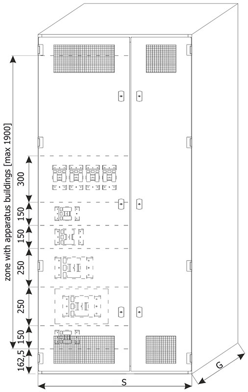
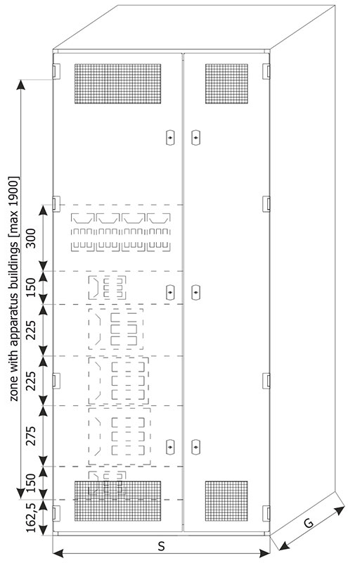
| Possibility of installing devices: | |
| Bay height | The device may be installed in a unit |
| 150 mm | Stationary compact circuit breaker up to 160 A Box fuse switch disconnector up to 160 A Modular device |
| 200 mm | Plug-in compact circuit breaker up to 160 A Plug-in stationary compact circuit breaker up to 250 A |
| 250 mm | 3-pole stationary compact circuit breaker up to 630 A 3-pole plug-in or withdrawable compact circuit breaker up to 400 A 3-pole box fuse switch disconnector up to 400 A |
| 300 mm | Four fuse switch disconnectors or compact circuit breakers installed vertically (current ≤ 160 A) Plug-in stationary compact circuit breaker up to 800 A 3-pole plug-in or withdrawable compact circuit breaker up to 630 A Electrical energy meters Various devices |
In a cabinet with a height of 2200 mm the device installation area is 1900 mm
In a cabinet with a height of 1900 mm the device installation area is 1500 mm
Free installation bay
| Technical data of the free instalation bay: | ||
| Area of application | The bay to be equipped by the customer | |
| Protection rating | Ventilated up to Ip41 Non-ventilated up to IP54 |
|
| Bay dimensions | Height Width Depth |
1900 / 2200 mm 400*) / 500 / 600 / 700 / 800 / 900 / 1000 / 1100 / 1200 mm 600 / 800 / 1000 mm |
| Possibility of installing devices |
The bay is designed for the installation of customer's devices, such as: frequency converters, softstarts, non-typical control instrumentation, etc. |
|
| Form of compartments | Form 2A | |
| Bay construction method | ||
| Primary busbars placed at the top | Bay depth 600 | Connection: - cables from the bottom, cable cross-sections according to the client specification |
| Primary busbars placed at the back | Bay depth 600 | Connection: - cables from the bottom or top, cable cross-sections according to the client specification |
| Every placement of primary busbars | Bay depth 800 / 1000 | Connection: - cables from the bottom or top, cable cross-sections according to the client specification |
*) Solution only for bays with busbars at the back.
MCC type cassette bay
| MCC type cassette bay electrical data: | ||
| Rated impulse | ||
| Rated insulation voltage Ui - main circuits - auxiliary circuits |
1000 V AC 500 V |
|
| Rated connection voltage Ue | do 690 V AC | |
| Rated impulse withstand voltage Uimp | 8 kV | |
| Overvoltage category | III / IV | |
| Level of contamination | 3 | |
| Rated frequency | 50 / 60 Hz | |
| Rated current | ||
| Distribution busbars | Rated current Ie | 1250 A |
| Rated short-time withstand current Icw | 65 kA | |
| Rated peak withstand current Ipk | 150 kA | |
| Resistance to electric arc effects | ||
| “Arc fault free” design prevents the occurrence of an arc fault. | ||
| MCC type cassette bay mechanical data: | ||
| Dimensions | ||
| Support cabinet and construction | Height | 2200 mm |
| Height of cassettes installation space | 1650 mm | |
| Widht | 1000, 1100, 1200 mm | |
| Depth | 600, 800, 1000 mm | |
| Surface protection | ||
| Supporting structures (profiles) | Zinc or Aluzinc coated | |
| Ingress protection rating | ||
| Depending on installation conditions | up to IP30 | |
| Plastic components | ||
| Halogen-free, self-extinguishing, fire-resistant, CFC-free | ||
| Form of compartments | ||
| Depends on the solution adopted | from 3B to 4B | |
| Cable compartment | ||
| Cable connection | right side of the bay | |
| Cable outlet | bottom or top | |
More details can be found in the Low voltage switchgears catalog in "Download" page
Capacitor bank bay
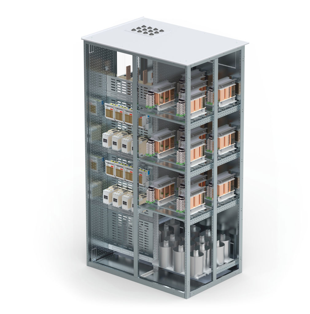
| Technical data of the capacitor bank bay: | ||
| Area of application | A capacitor or reactor bank with a power of 160 to 600 kvar - from 160 kvar to 460 kvar adjusted every 20 kvar - 500 / 550 / 600 kVA adjusted every 25 kvar |
|
| Ingress protection rating | Ventilated up to IP31 | |
| Bay dimensions | Height Width Depth |
1900 / 2200 mm 600 / 800 / 1000 / 1200 mm 600 / 800 / 1000 mm |
| The possibility of installing capacitor stages or capacitor and reactor stages. |
Using various sizes of bank stages | |
| Reactor-free | Reactor-based | |
| 5 kvar | 10 kvar | |
| 10 kvar | 15 kvar | |
| 15 kvar | 20 kvar | |
| 20 kvar | 25 kvar | |
| 30 kvar | 30 kvar | |
| 40 kvar | 40 kvar | |
| 50 kvar | 50 kvar | |
| 60 kvar | ||
| Form of compartments | Form 2A | |
| Bay construction method | ||
| The bank is connected in series with the main switchgear |
Busbar connection from the main busbars of the switchgear Cable connection fed in from the top or from the bottom |
|
| Separately standing bank | Cable connection fed in from the top or from the bottom | |
Note:
More information about capacitor bank bay can be found in chapter BK, BKD - Capacitor Banks
Corner bay
| Technical data of the corner bay: | ||
| Area of application | Connection bay of the switchgear cabinet in an L-shape | |
| Ingress protection rating | Ventilated up to IP31 Non-ventilated up to IP54 |
|
| Bay dimensions | Height Width Depth |
1900 / 2200 mm 700 / 900 / 1100 mm 700 / 900 / 1100 mm |
| Connection of busbar circuits in a top-mounted and rear-mounted system |
Upper busbar circuit 1600 / 2000 / 2500 / 3200 /4000 / 5000 / 6300 A Busbar circuit on the back 1600 / 2000 / 2500 / 3200 /4000 / 5000 / 6300 A |
|
| Form of compartments | Form 1 | |
| Cable connection | Not applicable | |
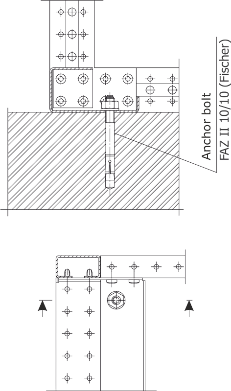
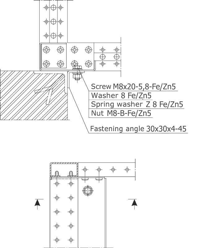
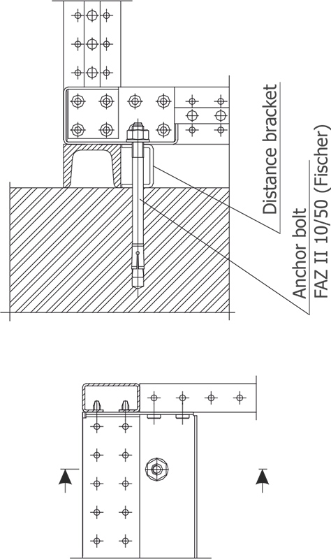
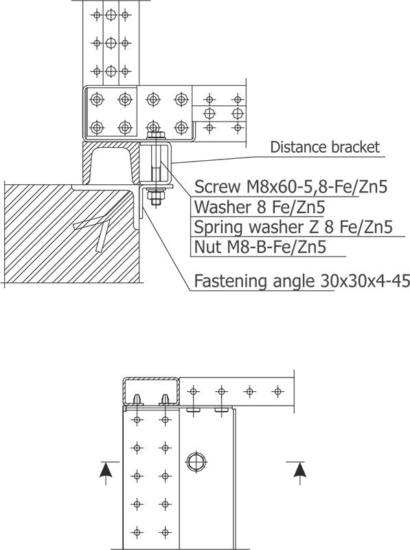
General conditions for location and placement of the switchgear
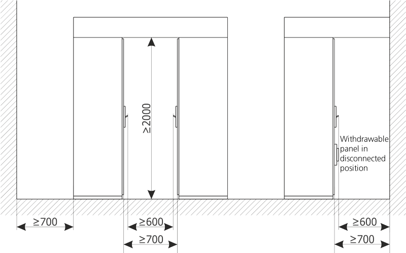
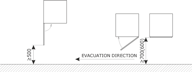

Placement
The foundation must be level, and its unevenness may not exceed 1 mm / 1000 mm.
The switchgear may be placed directly on the floor, on duct frame or on steel structure of the facility.
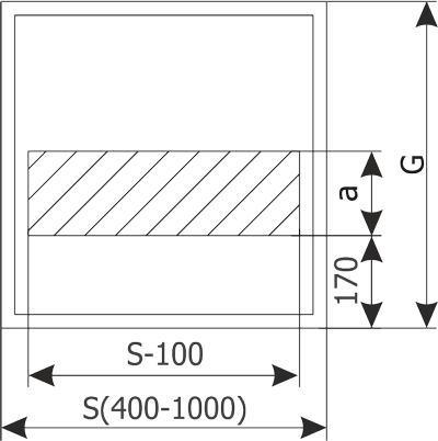
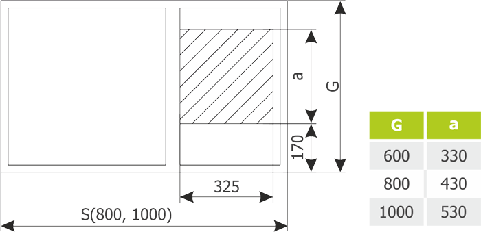
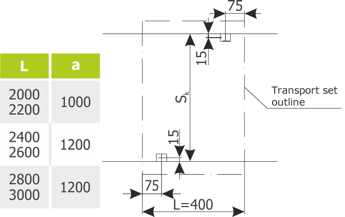
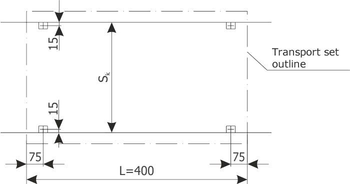
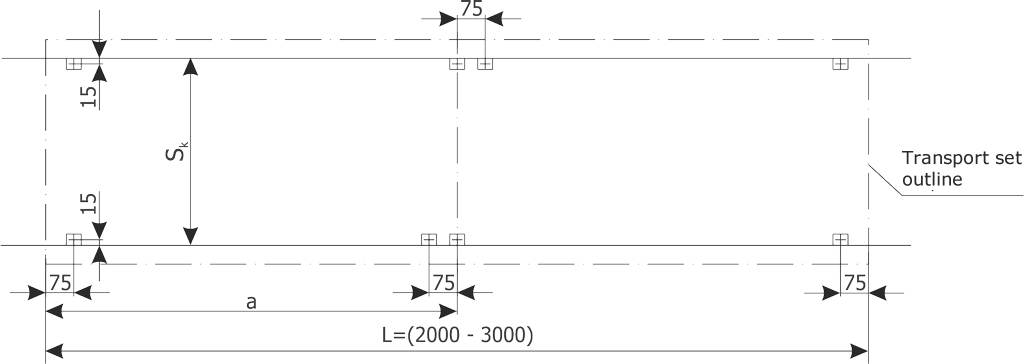
Sk - duct width Sk =(G-100)
G - depth of the switchgear cage (600, 800, 1000)