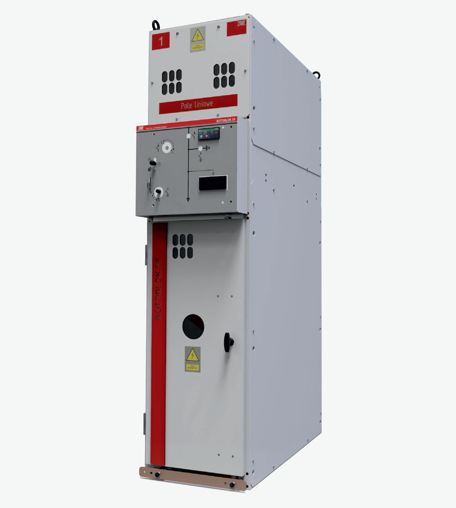
The subject of this document is a Rotoblok SF type state-of-the-art, indoor medium voltage switchgear intended for distribution of three-phase alternating current with a frequency of 50 Hz, at a rated voltage up to 25 kV, in industrial and commercial power sector distribution grids. The switchgears are configured from standard single modules with varied equipment. The information and technical data specified herein enable the designer to assemble a switchgear from typical modules. In case modules with equipment not specified herein or with changed dimensions are needed, the scope of equipment should be arranged with the manufacturer.
Method of cable duct construction under Rotoblok SF and rotoblok SF type MV switchgears
The Rotoblok SF type switchgear is a two compartment, indoors air insulated switchgear (AIS) in a mental enclosure made of zinccoated metal sheet (which ensures equipotential bonding), with a single primary busbars system. The switchgear is equipped with state-of-the-art, three-position disconnectors and switch disconnectors in SF6 insulation. The tank of each of these devices is constructed with stainless steel, which ensures maintaining a perfect technological condition of the switchgear over its entire operation period. It has separate primary busbars and cable compartments, and the arc-proof design ensures high level of operational safety.
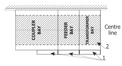
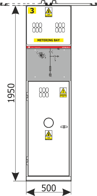
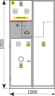
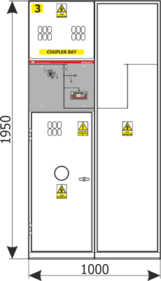
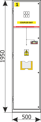
- Example bays.
- Cable duct under the switchgear.
| Cable cross-section (mm2) | Bending radius (mm) | Tray depth k (mm) |
| 50 | 370 | 400 |
| 70 | 400 | 430 |
| 95 | 440 | 470 |
| 120 | 470 | 500 |
| 150 | 500 | 550 |
| 185 | 540 | 600 |
| 240 | 590 | 700 |
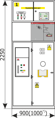
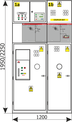
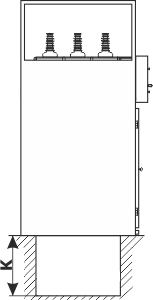
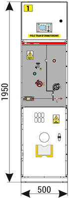
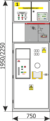
Construction of switchgear type Rotoblok SF
Side view and dimensions
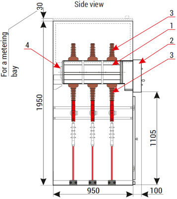
- - Stainless steel tank filled with SF6 gas with switching devices
- - Drive mechanism compartment
- - Insulating bushings
- - Safety valve
Note!
Figures shown on subsequent pages are only an example of bay equipment. It is possible to adapt the bay configuration to specific requirements of the end user. In this case manufacturer should be asked to provide drawings.
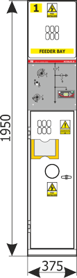
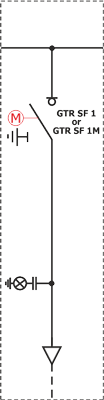
SL1 (line feeder)

Note!
Optional equipment is marked with red.
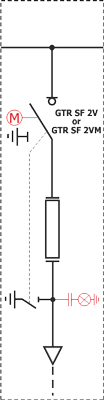
SL2 (line feeder)

Note!
Optional equipment is marked with red.
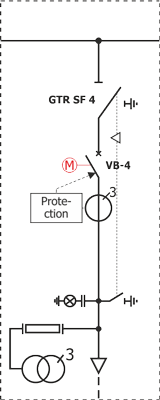
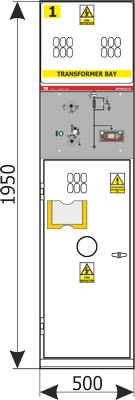
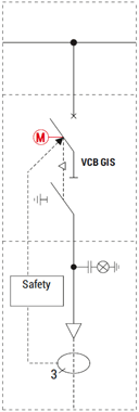
ST2 (transformer feeder)
Note!
Optional equipment is marked with red.
SP1 (metering unit)
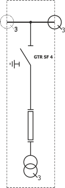
Note!
Optional equipment is marked with red.
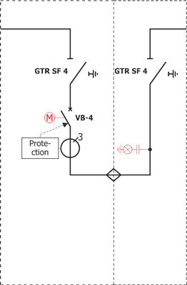
SS1L(P.*)) (bus coupler unit with disconnector or switch disconnector on the left side)
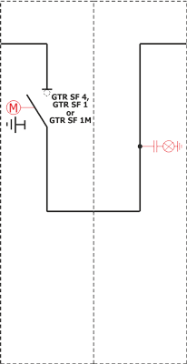
Note!
Optional equipment is marked with red. *) When post type current transformers are used instead of bushing type
SS2L(P.*)) (bus coupler unit with disconnector or switch disconnector on the left side)
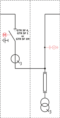
Note!
Optional equipment is marked with red. *) When post type current transformers are used instead of bushing type
SO1 (lightning arrester unit)

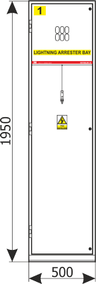
Note!
Optional equipment is marked with red.

STpwł4 (auxiliary transformer unit)
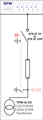
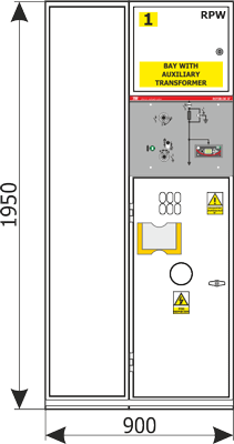
Note!
Optional equipment is marked with red.
STpwł 25kVA + ST1 (bay with an auxiliary transformer with a max. power of 25 kVA)
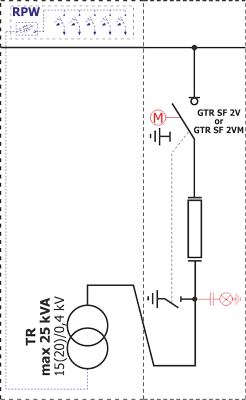
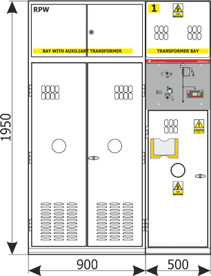
Note!
Optional equipment is marked with red.
SWG1 (circuit breaker feeder)
Note!
Optional equipment is marked with red.
SWTp(5*)) (circuit breaker transformer feeder)
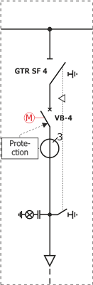
Note!
Optional equipment is marked with red. *) It is possible to design the unit in a mirror variant