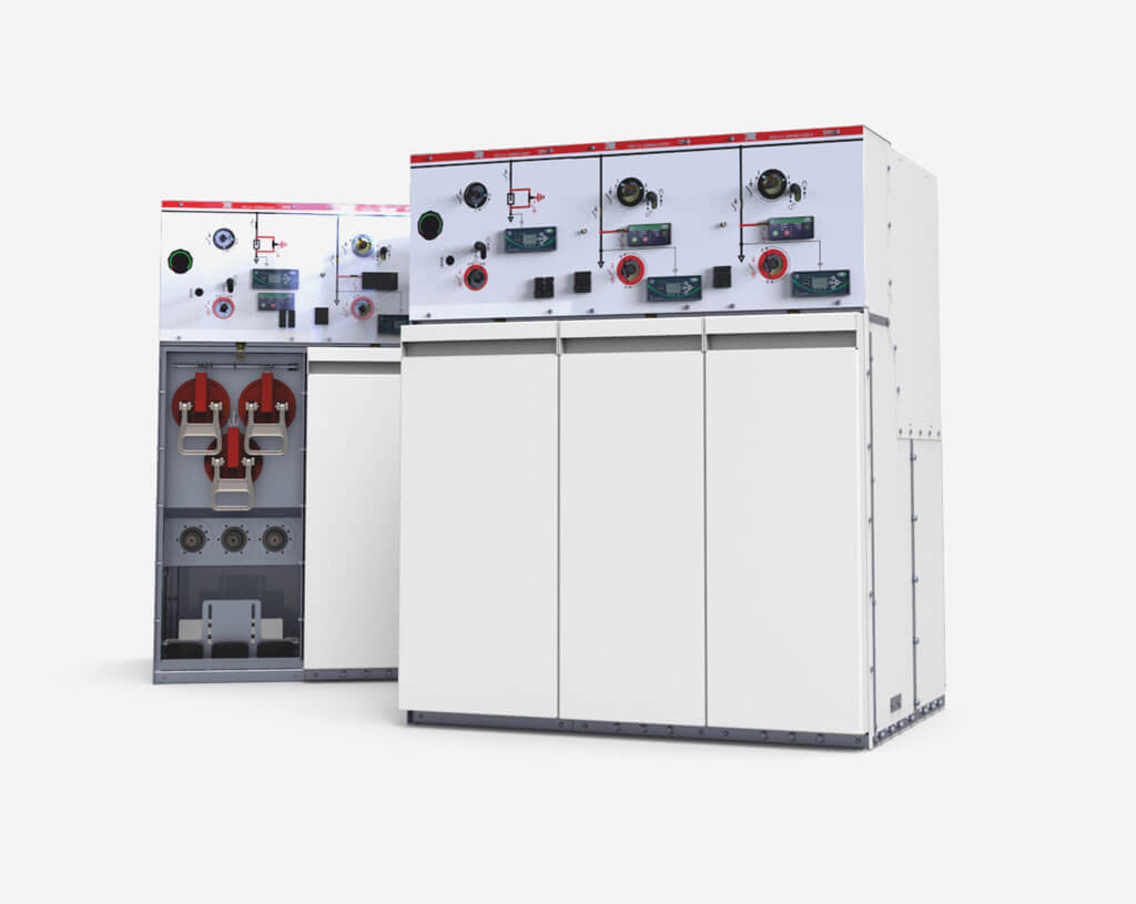
TPM series switchgear are a group of medium voltage ring type switchgear (RMU - Ring Main Unit), in SF6 gas insulation for use indoors. They are designed for supply and secondary distribution of electricity in radial and ring urban grids, in industry and in all facilities where compact switchgears with high technical parameters are very desirable. The switchgears are manufactured and tested based on the following standards. Type testing performed by independent accredited certification bodies. The test results are confirmed by appropriate certifications and test reports.
Characteristics
Characteristics
- miniature switchgear dimensions while maintaining high technical parameters,
- very high safety level, including arc protection - confirmed by appropriate certificates,
- possibility to configure the switchgear from a range of different purpose bays: feeder, transformer, circuit breaker, metering, cable bays,
- the possibility of configuring the switchgear with the use of a wide range of bays: feeder, transformer, circuit-breaker, bus coupler, metering,
- possibility of easily expanding the switchgear with additional assemblies (which should be taken into account when placing the order) each assembly may be manufactured as expandable,
- the possibility of adapting the switchgear to work with remote control and metering systems, e.g. to work in Smart Grid networks,
- fast earthing switch, which earths the fuse link on both sides in the transformer bay,
- the main SF6 gas tank is made of stainless, acid-resistant steel, with welded connections, which ensure environmental and 6 personal safety, and remain sealed over the entire period of switchgear operation,
- the manufacturer is able to recycle the waste switchgear and safely remove the SF6 gas from their tanks.
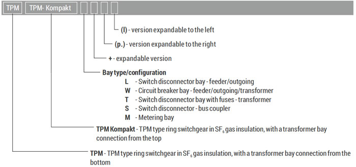
Possible markings/naming scheme
Safety
- robust construction of TPM type switchgear ensures high reliability,
- the tank is constructed of stainless, acid-resistant steel, ensuring resistance to environmental conditions,
- use of shielded terminations guarantees safety, e.g. during servicing operations with the front panel removed and live supply cables,
- gas pressure indicator - pressure meter which shows the correct pressure of insulating gas inside the tank,
- resistance to internal arc of 20 kA as a standard and 22 kA in custom design,
- pressure increase caused by internal arcing is eliminated by opening the safety valve installed in the lower part of the switchgear's tank. The gases are discharged to the cable duct, eliminating the hazard to personnel,
- each switchgear unit is equipped with voltage indicators, which enable the personnel to make sure that the insulating bushing terminals are not live,
- legible system display which improves intuitiveness of operation and facilitates reading the state of devices,
- a set of mechanical interlocks enables opening the front panels of the cable compartment only after the earthing switch is closed,
- a set of mechanical interlocks between the devices, which prevents performing incorrect switching operations,
- optional use of electromagnetic interlocks, which prevent the closing of the earthing switch with live supply cables,
- a set of auxiliary contacts with device state output, guaranteeing safety of remote operation,
- the use of pressure control at all times for the motor drive option guarantees safety of remote operation.
Field equipment
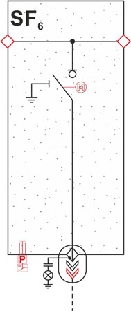
L - line feeder equipment
| Parameters | |
| Ur | = 25 kV |
| Fr | = 50/60 Hz |
| Ud | = 50/60 kV |
| Up | = 125/145 kV |
| Ir | = 630 A |
| Ik | = do 20 kA |
| Ip | = do 50 kA |
| IA | = do 22 kA |
| switch disconnector class M2, E3 | |
| earthing switch class M0, E2 | |
| Electrical data of line functional unit (L) | ||
| Continuous rated current | Ir | 630 A |
| Rated short-circuit making current | Ima | 50 kA |
| Rated low inductance circuit breaking current | Iload | 630 A |
| Rated ring network circuit breaking current | Iloop | 630 A |
| Rated buried cable charging breaking current | Iicc2 | 60 A |
| Rated overhead line charging breaking current | Iicc1 | 20 A |
| Rated earth fault breaking current | Ief1 | 180 A |
| Rated buried cable and overhead line charging breaking current in earth fault conditions | Ief2 | 104 A |
| Switch disconnector class | M2, E3 | |
| Earthing switch class | M0, E2 | |
- meets the requirements of the PN-EN 62271-103 Switches for rated voltages above 1 kV up to and including 52 kV standard,
- the L unit as a single module with option of expanding, in almost any configuration up to four units in a common tank,
- disconnector-earthing switch unit, the construction of which is based on common moving contacts and separated fixed contacts of the earthing switch and switch disconnector,
- switch disconnector with a switching operations arc quenching system,
- manual double spring drive which ensures intuitive and easy operation and snap-action closing and opening of the switching devices,
- system display representing the state of devices and entire primary circuits,
- type C insulating bushings with M16 thread, equipped with capacitive voltage dividers intended for operation with voltage indicators in the LRM system and to operate with electromagnetic interlocks,
- cable voltage indicator in the LRM system,
- pressure meter - gas pressure indicator with a scale with two zones, indicating the rated absolute pressure of the SF6 gas - 125 kPa (0.125 MPa) at a temperature of 20°C (one per one 6 tank),
- a system of mechanical interlocks between the devices and front panels of the cable compartment preventing incorrect switching operations - removing the front panel only after closing the earthing switch,
- safety valve (one per one tank), which is opened by pressure increase caused by arcing inside the tank, directing the gases downwards, to the cable duct, eliminating the hazard to personnel,
- cable clamps.
- 24 V DC motor drive (other supply voltage on request), possibility of easy expansion at the facility,
- pressure control - for operating with motor drive, telemetry,
- SEM SC 11 field controller plus local control panel, Modbus communication or binary communication
- auxiliary contacts as representation of state of devices for telemetry systems,
- voltage sensors - low power transformers,
- current transformers, Rogowski coils,
- earth fault transformers,
- short-circuit current indicators,
- auxiliary circuits cubicle/operation with telemetry,
- “ON”, “OFF” signalling in the form of signalling lamps,
- anti-condensation heaters,
- possibility of expanding on the left and right side,
- key interlock of the switch disconnector or earthing switch socket,
- electromagnetic interlock of the earthing switch socket,
- overvoltage limiters.
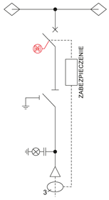
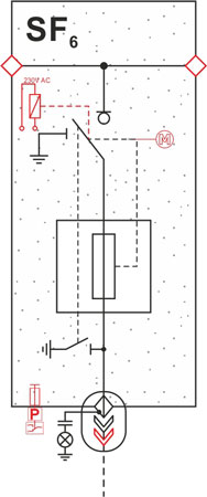
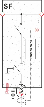
T - tansformer feeder equipment
| Parameters | |
| Ur | = 25 kV |
| Fr | = 50/60 Hz |
| Ud | = 50/60 kV |
| Up | = 125/145 kV |
| Ir | = 250 A (125 A fuse link) |
| Ik | = 20 kA (1s) |
| Ip | = 50 kA |
| IA | = do 22 kA |
| Itransf | = 720 A |
| switch disconnector class M2, E3 | |
| Electrical data of the fused transformer functional unit (T) | |||
| Continuous rated current | Ir | 250 A | |
| Maximum thermally protected fuse link current | 125 A | ||
| Through-current | Itransfer | 720 A | |
| Switch disconnector electrical class | M2, E3 | ||
| Maximum transformer power | 6 kV | 800 kVA | |
| 10 kV | 1000 kVA | ||
| 15 kV | 1600 kVA | ||
| 20 kV | 2000 kVA | ||
- meets the requirements of the PN-EN 62271-105 Alternating current switch-fuse combinations standard
- the T unit as a single module with option of expanding, in almost any configuration up to four units in a common tank,
- disconnector-earthing switch unit, the construction of which is based on common moving contacts and separated fixed contacts of the earthing switch and switch disconnector,
- lower earthing switch, ensuring earthing on both sides of the fuse links,
- switch disconnector with a switching operations arc quenching system,
- manual double spring drive which ensures intuitive and easy operation and snap-action closing and opening of the switching devices,
- system display representing the state of devices and entire primary circuits,
- stored energy release mechanism function, which allows the switch disconnector contacts to be opened when MV fuse links with thermal protection (striker) or a tripping coil is used,
- blown fuse link indicator,
- type A insulating bushings with plug-in socket, equipped with capacitive voltage dividers intended for operation with voltage indicators in the LRM system and to operate with electromagnetic interlocks,
- cable voltage indicator in the LRM system,
- a system of mechanical interlocks between the devices and front panels of the cable connection compartment preventing incorrect switching operations - removing the front panel only after the earthing switch is closed,
- safety valve (one per one tank), which is opened by pressure increase caused by arcing inside the tank, directing the gases downwards, to the cable duct,
- cable clamps.
- 24 V DC motor drive (other supply voltage on request), possibility of easy expansion at the site,
- pressure control - for operating with motor drive, telemetry,
- SEM SC 11 field controller plus local control panel, binary or Modbus communication,
- auxiliary contacts as representation of state of devices for telemetry systems,
- fuse links with integrated temperature limiter (thermal trip), acc. to the IEC 60282-1, DIN 43625 standard, e.g. by SIBA
- voltage sensors - low power transformers,
- current transformers, Rogowski coils,
- “ON”, “OFF” signalling in the form of signalling lamps,
- anti-condensation heaters,
- possibility of expanding on both sides,
- key interlock of the disconnector or earthing switch socket,
- electromagnetic interlock of the earthing switch socket, option dedicated for renewable energy system,
- shunt trip - DWN 24 V DC coil, 230V AC/DC (other voltages on request).
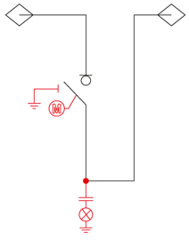
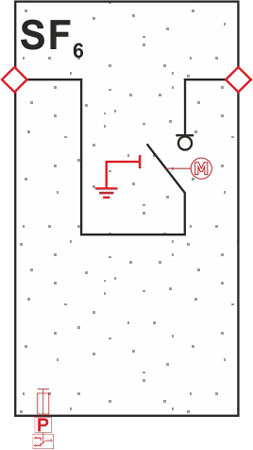
W - circuit breaker feeder
| Parameters | |
| Ur | = 25 kV |
| Fr | = 50/60 Hz |
| Ud | = 50/60 kV |
| Up | = 125/145 kV |
| Ir | = 630 A |
| Ik | = do 20 kA (1s) |
| Isc | = do 50 kA |
| Icc1 | = 10 A |
| Icc2 | = 31,5 A |
| circuit braker class M2, E2 | |
| operating sequence duty cycle (O-0, 3s-CO-3min-CO) | |
| Electrical data of circuit breaker feeder (W) | ||
| Continuous rated current | Ir | 630 A |
| Short-circuit making current | Ima | 40 kA / 50 kA / 52,5 kA *1) |
| Short-circuit breaking current | Isc | 16 kA / 20 kA / 21 kA *1) |
| Rated low inductance circuit breaking current | 630 A | |
| Cable line current with no load - Icc1 / Icc2 | Icc1 / Icc2 | 10 A / 31,5 A |
| Circuit breaker class | M2, E2 | |
| Operating sequence duty cycle | 0-0, 3s-CO-3min-CO | |
Custom design:
1) For 12 kV voltage.
- meets the requirements of the PN-EN 62271-100 Alternating current circuit-breakers standard,
- meets the requirements of the PN-EN 62271-102 Alternating current disconnectors and earthing switches standard,
- the W bay as a single module with option of expanding, in almost any configuration up to four bays in a common tank,
- circuit breaker unit, the construction of which is based on the use of vacuum chambers with a breaking current of 16 kA or 20 kA, enclosed in an SF6 gas filled tank,
- disconnector-earthing switch unit, the construction of which is based on common moving contacts and separated fixed contacts of the earthing switch and disconnector. The function of the disconnector is to ensure a safe gap in the circuit,
- manual spring drive of the circuit breaker, which ensures intuitive and easy operation and snapaction closing and opening of the switching devices, the drive has a charging system which allows a rapid breaker on-off cycle,
- manual spring-less drive of the disconnector and earthing switch, which ensures intuitive and easy operation of the switching devices,
- system display representing the state of devices and entire primary circuits,
- circuit breaker charging indication,
- independent protection, preferably AZZ-4 (by ITR) or WIC 1 (by Woodward) with dedicated current transformers,
- type C insulating bushings with M16 thread, equipped with capacitive voltage dividers intended for operation with voltage indicators in the LRM system and to operate with electromagnetic interlocks,
- cable voltage indicator in the LRM system,
- pressure meter - gas density indicator with a scale with two zones, indicating the rated absolute pressure of the SF6 gas - 125 kPa (0.125 MPa) at a temperature of 20°C (one per one tank),
- a system of mechanical interlocks between the devices and front panels of the cable compartment preventing incorrect switching operations - removing the front panel only after closing the earthing switch,
- safety valve (one per one tank), which is opened by pressure increase caused by arcing inside the tank, directing the gases downwards, to the cable duct, eliminating the hazard to personnel,
- cable voltage indicator,
- cable clamps.
- 24V DC motor drive for the circuit breaker and for the disconnector and earthing switch (other supply voltage on request),
- pressure control - for operating with motor drive, telemetry,
- auxiliary contacts as representation of state of devices for telemetry systems,
- protections other than preferred independent, unit controllers, ATS automation,
- voltage sensors - low power transformers,
- current transformers, Rogowski coils,
- earth fault transformers,
- auxiliary circuits cubicle/operation with telemetry,
- “ON”, “OFF” signalling in the form of signalling lamps,
- anti-condensation heaters,
- possibility of expanding on both sides,
- overvoltage limiters.
S - bus sectionalizer panel
| Parameters | |
| Ur | = 25 kV |
| Fr | = 50/60 Hz |
| Ud | = 50/60 kV |
| Up | = 125/145 kV |
| Ir | = 630 A |
| Ik | = do 20 kA (1s) |
| Ip | = 50 kA |
| IA | = do 22 kA |
| switch disconnector class M2, E3 | |
| earthing switch class M0, E2 | |
- meets the requirements of the PN-EN 62271-103 Switches for rated voltages above 1 kV up to and including 52 kV standard,
- the S unit as a single module expandable both to the right and to the left,
- disconnector, the construction of which is based on common moving contacts and on fixed contacts,
- switching operations arc quenching system,
- manual single or double spring drive (depending on the use of an earthing switch), which ensures intuitive and easy operation and snap-action closing and opening of the switching device,
- system display representing the state of devices and entire primary circuits,
- pressure meter - gas density indicator with a scale with two zones, indicating the rated absolute pressure of the SF6 gas - 125 kPa (0.125 MPa) at a temperature of 20°C (one per one tank),
- safety valve (one per one tank), which is opened by pressure increase caused by arcing inside the tank, directing the gases downwards, to the cable duct, eliminating the hazard to personnel.
- 24 V DC motor drive (other supply voltage on request), possibility of easy expansion at the facility,
- earthing switch of the primary circuit of the right section,
- primary circuits (before and after the disconnector) voltage indicator,
- pressure control - for operating with motor drive, telemetry,
- SEM SC 11 field controller plus local control panel, binary or Modbus communication,
- auxiliary contacts as representation of state of devices for telemetry systems,
- anti-condensation heaters,
- possibility of expanding on both sides,
- key interlock of the disconnector or earthing switch socket.
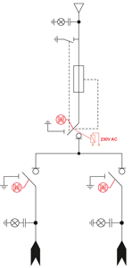
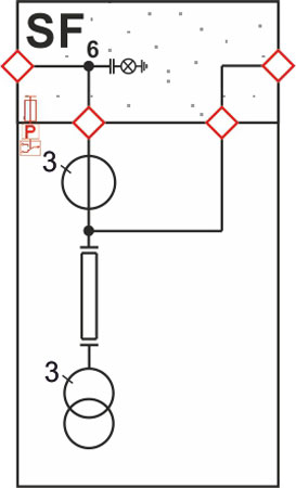
M - metering panel equipment
| Parameters | |
| Ur | = 25 kV |
| Fr | = 50/60 Hz |
| Ud | = 50/60 kV |
| Up | = 125/145 kV |
| Ir | = 630 A |
| Ik | = do 20 kA (1s) |
| Ip | = do 50 kA |
- meets the requirements of the PN-EN 62271-200 AC metal-enclosed switchgear and controlgear for rated voltages above 1 kV and up to and including 52 kV standard,
- the M unit as a single module expandable both to the right and to the left,
- a system of primary busbars enclosed in a stainless steel tank,
- a set of current transformers and voltage transformers,
- primary circuits voltage indicator,
- system display representing the state primary circuits,
- pressure meter - gas density indicator with a scale with two zones, indicating the rated absolute pressure of the SF6 gas - 125 kPa (0.125 MPa) at a temperature of 20°C (one per one tank),
- safety valve (one per one tank), which is opened by pressure increase caused by arcing inside the tank, directing the gases downwards, to the cable duct, eliminating the hazard to personnel.
- pressure control - for operating with motor drive, telemetry,
- anti-condensation heaters,
- option of connecting with side connectors or cable terminations.
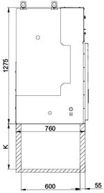
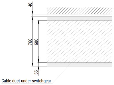
Construction method for a cable duct under the TPM type MV switchgears
Figures 1–3 present a cable duct construction proposal. The cable bending radius (which depends on its outside diameter, according to PBUE) should be taken into account when establishing the dry cables duct depth. Figure 1 shows the suggested cable duct depth. It is possible to avoid or reduce the depth of the cable duct by using a raised base or a raised floor.
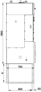
| Cable cross section (mm2) | Bending radius (mm) | Duct depth K (mm) |
| 50 | 370 | 400 |
| 70 | 400 | 430 |
| 95 | 440 | 470 |
| 120 | 470 | 500 |
| 150 | 500 | 550 |
| 185 | 540 | 600 |
| 240 | 590 | 700 |
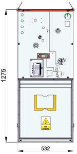
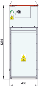
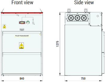
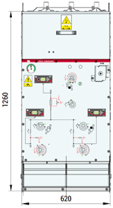
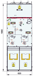
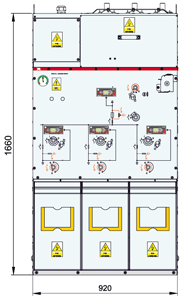
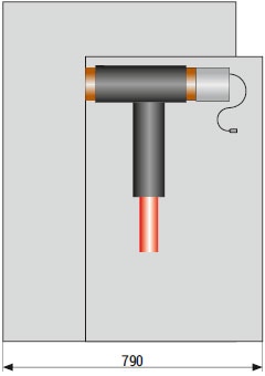
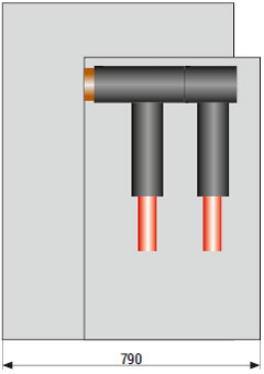
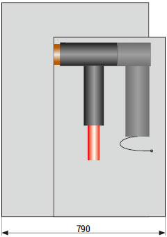
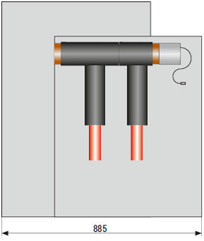
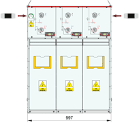
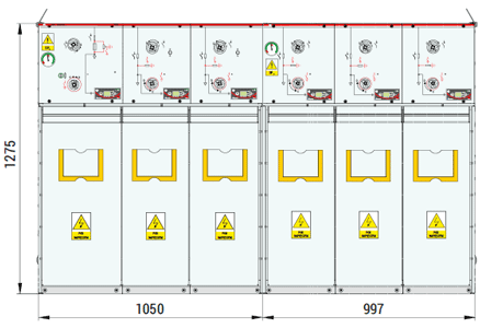
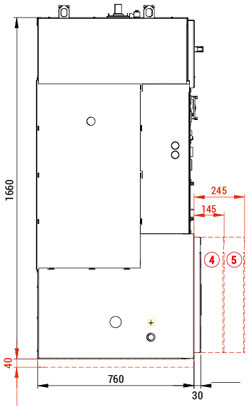
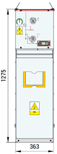
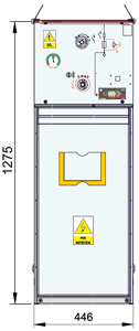
Approximate dimensions / TPM switchgear connection options


Expandable units connection method
The TPM switchgear can be expanded with additional assemblies (on the condition that this was discussed at the pricing and ordering stage). The examples of connection methods were presented on figures below. Detailed information is provided in the Switchgear Operation & Maintenance Manual.
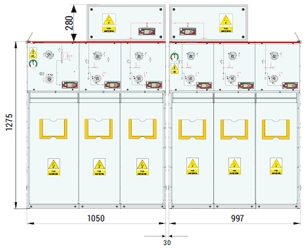
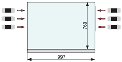
TPM switchgear side views and dimensions
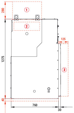
1) - cover for TPM switchgear in expandable version - top connection,
2) - cover for TPM switchgear in expandable version - side connection,
3) - front panel depth of 125 mm used only in case of:
Double termination with a voltage sensor;
Termination with overvoltage limiter and voltage sensor;
K400LB termination with a 400PB overvoltage limiter.
4) - front panel depth in case of use termination with with overvoltage limiter,
5) - front panel depth in case of use termination with with overvoltage limiter and voltage sensor.
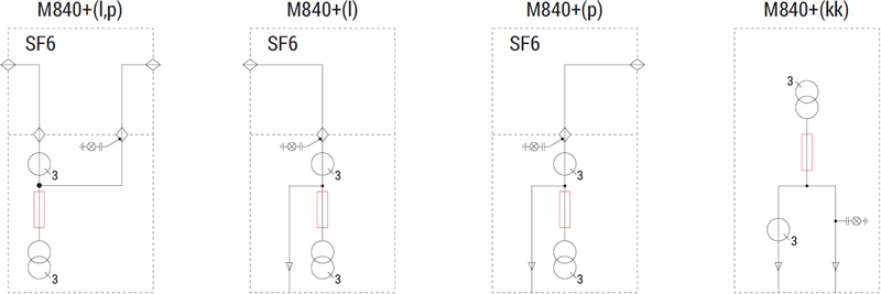
TPM - typical configurations
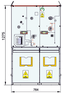
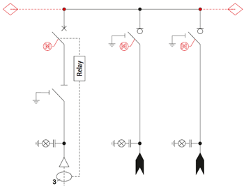
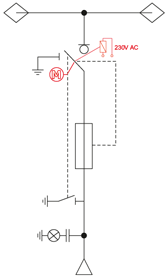
TL / LT configuration (transformer feeder, line feeder)
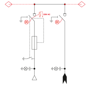
Optional equipment was marked with red on the electrical diagram.
TLL / LLT configuration (transformer feeder, 2 line feeders)
Optional equipment was marked with red on the electrical diagram.
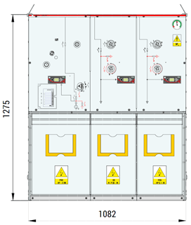
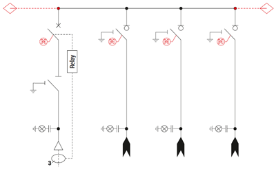
TLLL / LLLT configuration (transformer feeder, 3 line feeders)
Optional equipment was marked with red on the electrical diagram.
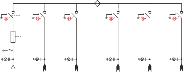
TLLT configuration (2 transformer feeders, 2 line feeders)
Optional equipment was marked with red on the electrical diagram.
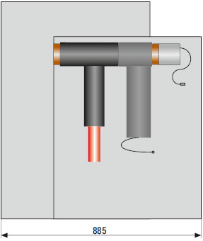
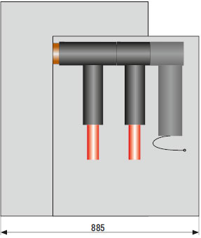
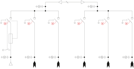
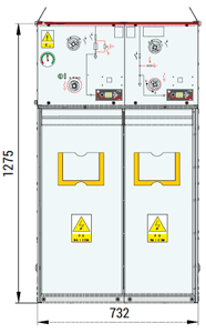
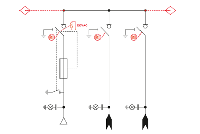
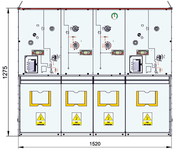
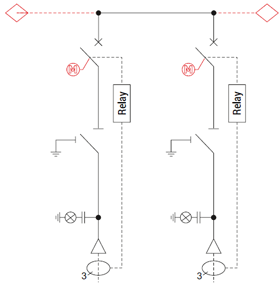
TT configuration (2 transformer feeders)
Optional equipment was marked with red on the electrical diagram.
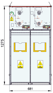
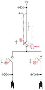
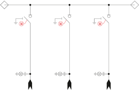
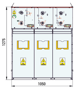
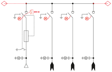
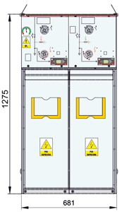
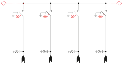
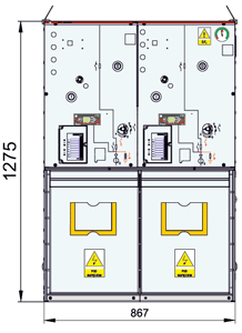
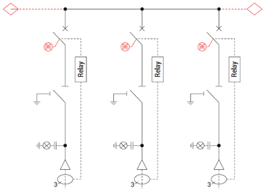
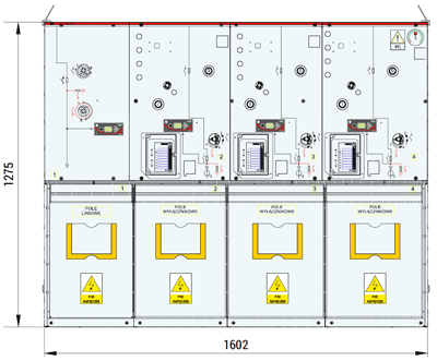
LLL configuration (3 line feeders)
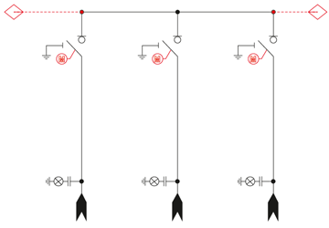
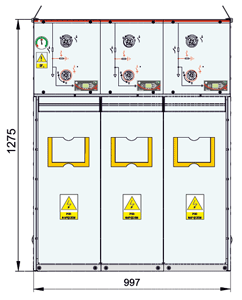
Optional equipment was marked with red on the electrical diagram.
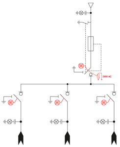
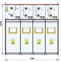
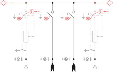
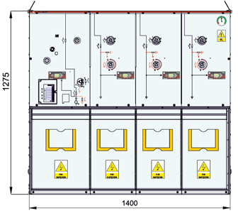
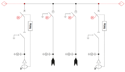
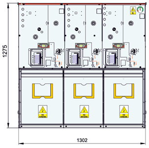
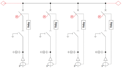
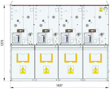
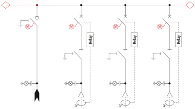
LLLL configuration (4 line feeders)
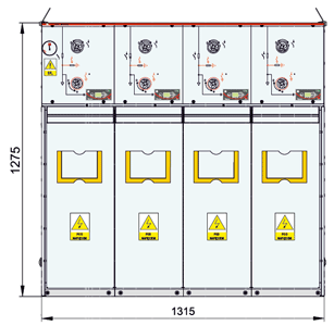
Optional equipment was marked with red on the electrical diagram.
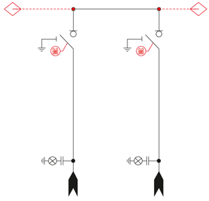
WL / LW configuration (circuit breaker feeder, line feeder)
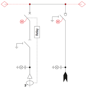
Optional equipment was marked with red on the electrical diagram.
WLL / LLW configuration (circuit breaker feeder, 2 line feeders)
Optional equipment was marked with red on the electrical diagram.
WLLL / LLLW configuration (circuit breaker feeder, 3 line feeders)
Optional equipment was marked with red on the electrical diagram.
WLLW configuration (2 circuit breaker feeders, 2 line feeders)
Optional equipment was marked with red on the electrical diagram.
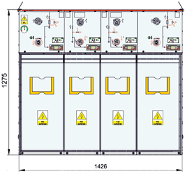
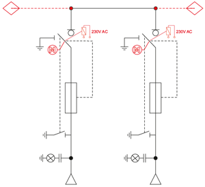
WW configuration (2 circuit breaker feeders)
Optional equipment was marked with red on the electrical diagram.
WWW configuration (3 circuit breaker feeders)
Optional equipment was marked with red on the electrical diagram.
TPM - typical configurations - single units
L+ (p,l) configuration (line feeder)
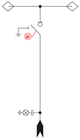
Optional equipment was marked with red on the electrical diagram.
T+ (p,l) configuration (transformer feeder)
Optional equipment was marked with red on the electrical diagram.