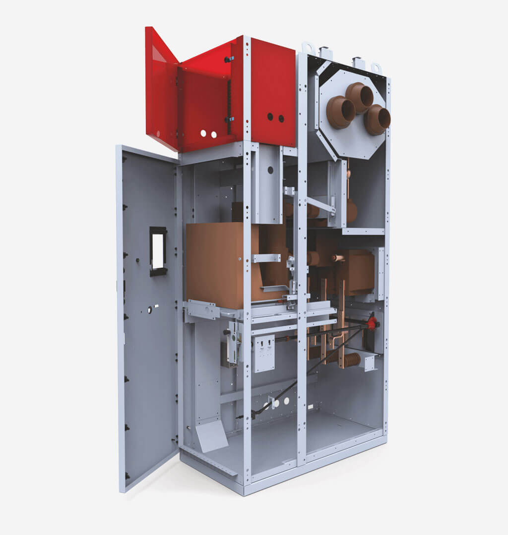
The page presents medium voltage switchgear type RXD:
- air insulated,
- metal enclosed,
- withdrawable or fixed module - depending on equipment,
- with a single busbar system,
- for rated voltages of 12 kV or 36 kV,
- for indoor use.
Highest performance enclosed in an air insulated metal casing. Medium voltage switchgear type RXD works perfectly with up to 36kV, remaining suitable for distribution transformer stations in electric power plants. Thanks to an easy operation, high configurability as well as possibility to expand using additional bays, this ZPUE solution provides great results, while remaining adjustable to electric power industry’s needs. It has been also equipped with withdrawable module that can consist of e.g. contactor, circuit breaker and a set of voltage transformers with fuses.
Designed for rated voltage up to 36kV, the switchgear has been equipped with an additional internal measures to ensure the highest safety of operation. Including a special withdrawable module (allowing maneuvering even when the casing's door is closed), housing resistant to internal arcs and dedicated door-opening interlocks. Thanks to uninterrupted operation even during servicing, we can guarantee the highest efficiency at all times. The correct usage of provided equipment reduces the risk of damage or operator’s injury.
Switchgear design
Switchgear design
Design
- The switchgear cubicle is constructed of bent steel sheets, riveted together. Walls and partitions create a self-supporting structure. Zinc-coated sheet is used for the construction of cubicles.
- High-strength round-head steel rivets were used as fasteners.
- Additionally, two-part side covers made of painted sheet are bolted to the external walls of the outer bays of the switchgear.
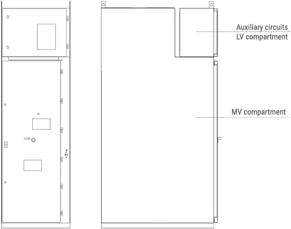
- An auxiliary circuits compartment is placed on top of the cabinet.
- Each cubicle is fully separated from the adjacent cabinets, which prevents damage spreading to adjacent cubicles in case of an electric arc.
- Main busbars are located at the top of the cabinet. The busbars pass between the cabinets through gland plates made of non-magnetic material and equipped with bushings, which are support elements for the main busbars. Outgoing busbars branch off the main busbars.
- The main busbars area can be isolated during servicing by inserting an insulating plate into guide-rails through a slot located above the door (there is also an option of construction of a switchgear with a separate main busbar compartment).
- The cubicle doors may be opened in an interlock-controlled mode.
- The main device may be fixed or as a withdrawable module. The withdrawable module in the operating and test/disconnection positions is located inside the cabinet, behind closed doors. After the doors are opened, it is possible to rack it out to the separation position.
- Mechanical indicators of the circuit breaker position and drive charging state are visible through the inspection window in the switchgear doors.
- In accordance with the LSC (Loss of Service Continuity) classification, the RXD switchgear meets the criteria of LSC2 class (for 12 kV) and LSC1 for 36 kV.
- Connections for cables or busbars are located in the lower zone of the cabinet. It also contains current transformers, fast earthing switch (RXD 12 kV) and depending on operational needs, optionally: voltage transformers, earth fault transformersand surge arresters.
- The earthing switch status is indicated by a position indicator.
- The cubicle bottom is closed by a split floor cover, which also acts as a cable gland plate. Openings in the plate are covered with rubber cable glands.
- Cable clamp supports and earth fault transformer supports are installed on folds of the bottom plate.
The cubicle doors are made of painted sheet. Doors use hinges and bolts which can stand up to explosion-type loads.
The hinges allow opening the doors by approximately 135º.
The doors were reinforced by appropriately shaped and welded reinforcing profiles.
The doors are equipped with an inspection window used for visual control of the position of the withdrawable module and switching operations.
The design of the doors allows the mechanical opening of the circuit breaker in service position with the doors closed.
Safety flaps
The cabinet has in its top part blow-out openings, closed with flaps. Their task is to discharge any pressure created inside the cabinet as a result of an arc fault.
A sudden increase of pressure inside the switchgear cabinet breaks the plastic bolts and opens the flaps, which may activate limit switches installed at the roof of the switchgear. Limit switches activated by the flaps being opened send an impulse which trips the incoming feeder circuit breaker. This allows limiting the effects of an arc fault generated inside the cabinet.
The withdrawable module is a unit composed of a racking system, and depending on the bay function, respectively: circuit breaker, contactor, set of fused voltage transformers, or a sectionalizer. The racking system performs the mechanical connection of the withdrawable module with the switchgear bay. It's stationary part is connected with the bay by interlocking on both sides in guide rail cutouts.
The moving part of the racking system is shifted between the service position and the test/disconnection position using a drive screw operated manually with a crank, or with an electric drive, while the doors are closed. The service and test/disconnection position is signalled by position indicators, after the module reaches an appropriate position.
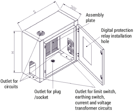
The auxiliary circuits compartment (low voltage compartment) is constructed in the form of a control cubicle and is completely separated from the high voltage zone of the switchgear. The cubicle has its own metal enclosure and may be prefabricated independently of the high voltage part of the switchgear.
The cubicle is intended for the installation of: protection relays and IEDs, instrumentation & control devices and automation system elements.
It is installed on the roof of the switchgear. In its bottom, top and side walls a series of openings are made for lead and cable glands and cable trays.
These openings are covered by plates, in which holes can be made according to design needs. An assembly plate fixed to the rear wall of the LV cubicle was designed for the installation of devices. The devices may be also fixed on the side walls.
On arrangement with the manufacturer, the cubicle design may be adapted to individual needs of the customer and of the design.
Busbars
Main busbars
A single, three-phase current circuit is used as a main busbar in the switchgear, located in the top, back part of the cabinet.
Copper flat bars with rounded edges were used, with cross-sections selected in accordance with the rated current of the switchgear.
The main busbars are supported by distribution busbars and on bushings installed in the side partitions.
Distribution busbars
Distribution busbars are made flat bars with rounded edges, with cross-sections selected in accordance with the rated current of the switchgear.
Insulating elements
The switchgear used epoxy resin insulators. These are post insulators used to support busbars and bushings used to pass the main busbars between the switchgear bays, installed in the gland plates of the bay side walls.
Protective earthing
A earthing conductor is placed in every cabinet, in the form of a copper busbar with a cross-section of 40x5 mm, placed at the bottom, in the rear of the cabinet. These busbars are bridged between the cabinets, creating an earthing conduit. This conduit is terminated with terminals on the left and right side of the switchgear, used to connect it to the facility's earthing system.
Cable connections
The cabinet connection is adapted for entry of single- or multi-core MV cables.
Drawings
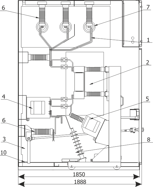
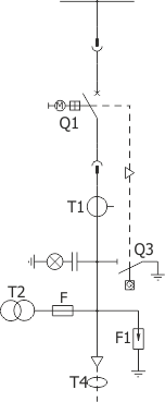
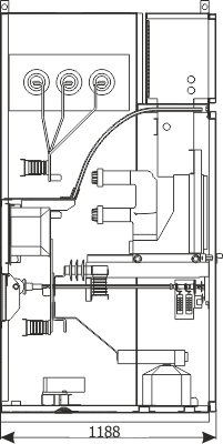
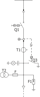
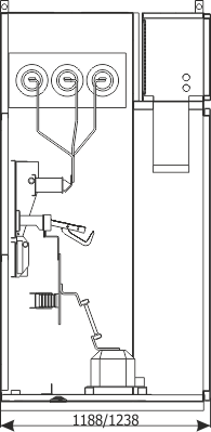
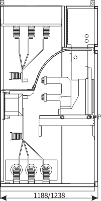
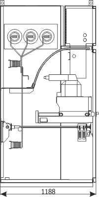
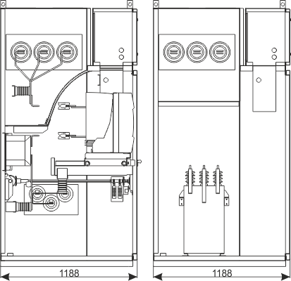
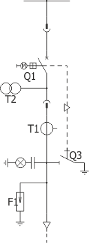
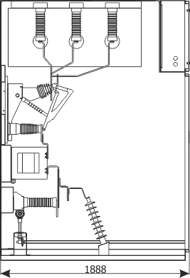
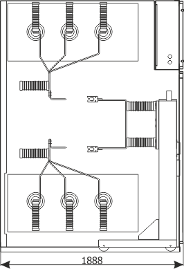
Figure 1a - Example equipment of the RXD 12 bay
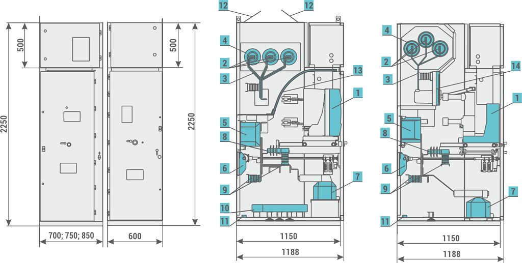
- main device: circuit breaker contactor
- main busbars
- outgoing busbars
- bushings
- current transformers
- earthing switch
- voltage transformers
- surge arresters
- capacitive post insulators
- earth fault transformer
- earthing busbar
- safety flaps
- insulating plate
- partition with insulator
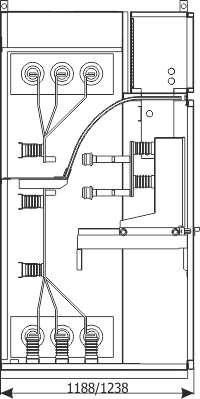
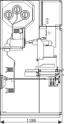
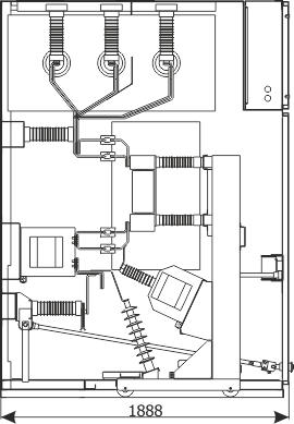
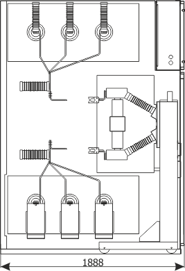
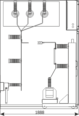
Figure 1b - Example equipment of the RXD 36 bay
- outgoing busbars
- primary device: circuit breaker
- earthing switch
- current transformers
- voltage transformers
- capacitive post insulators
- bushings
- surge arresters
- protection relay
- earthing busbar
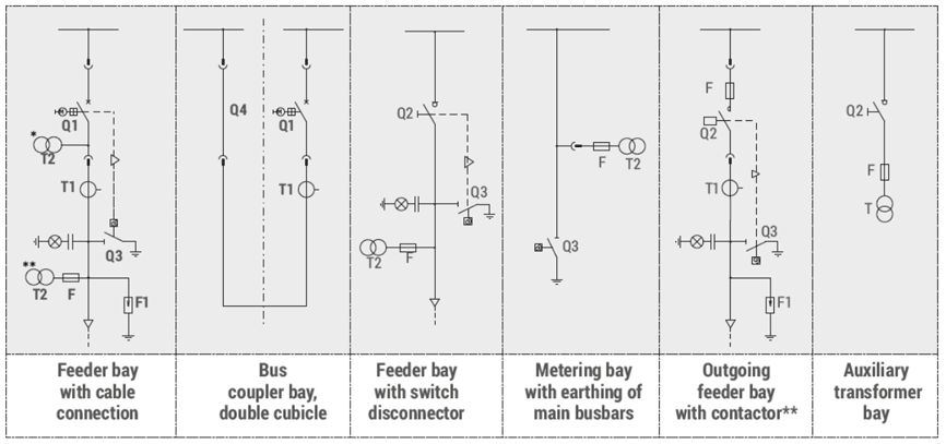
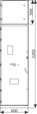
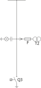
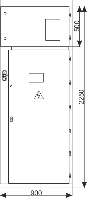
Figure 3a - RXD 12 bay auxiliary circuits compartment
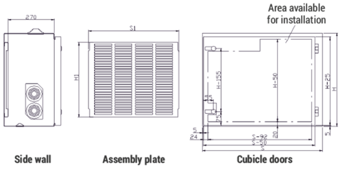
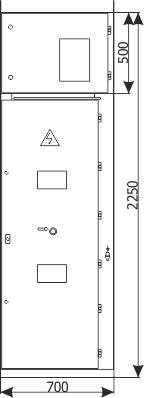
| Dimensions [mm] | ||||
| H | 500 | 500 | 500 | 500 |
| S | 900 | 750 | 700 | 600 |
| H1 | 450 | 450 | 450 | 450 |
| S1 | 820 | 670 | 630 | 520 |

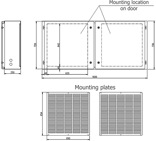
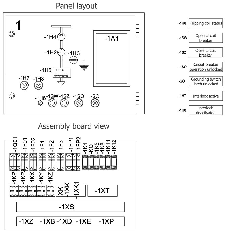
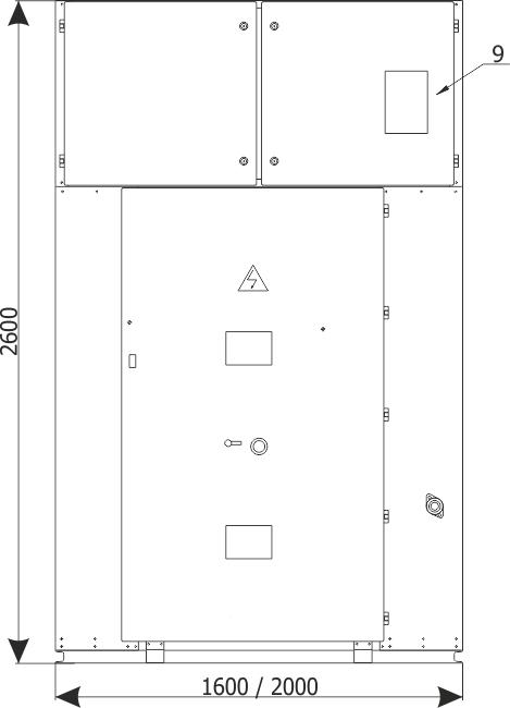
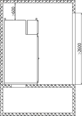
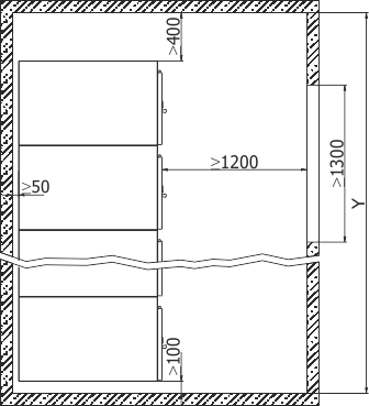
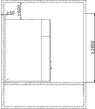
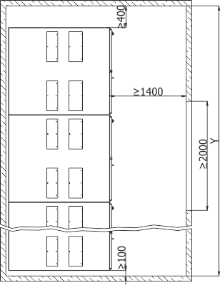
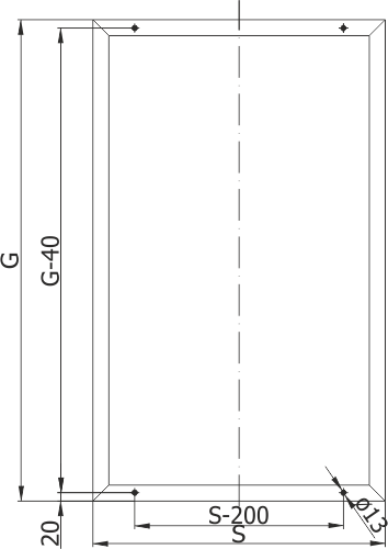
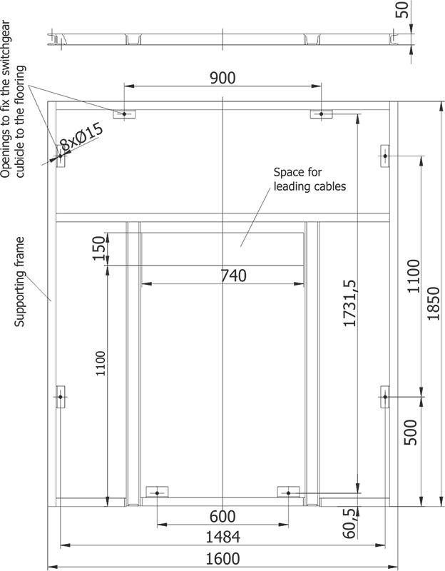
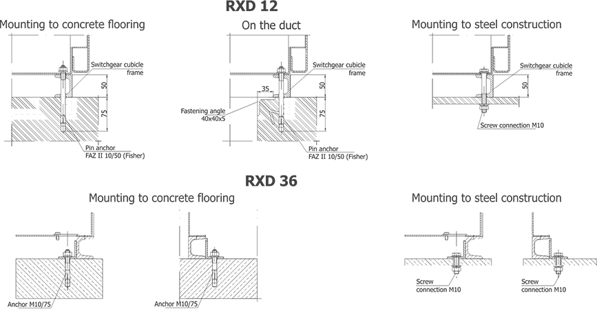
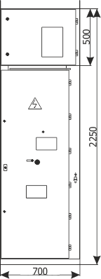
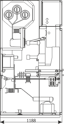
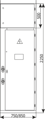
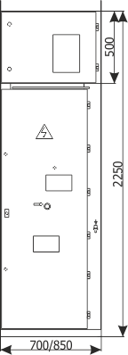
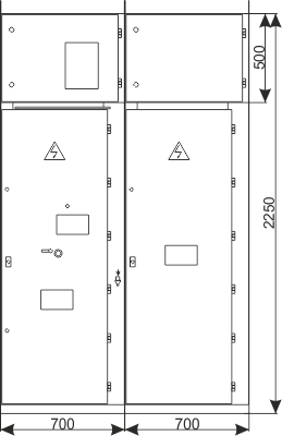
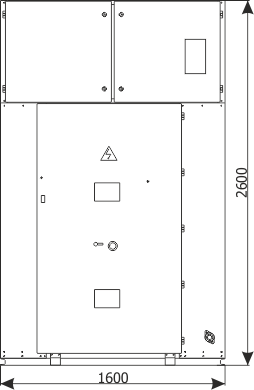
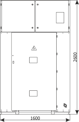
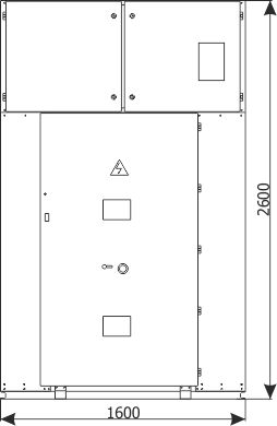
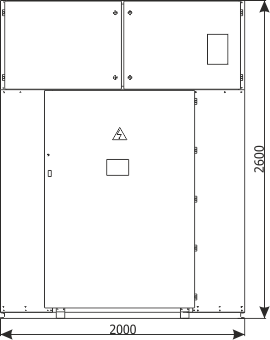
Figure 5a - Placement of the RXD 12 switchgear
Data sheets examples
RXD 12 kV
| RXD 12 kV | ||
| 1. | Sheet 1.1 | Feeder bay with circuit breaker, 12 kV |
| 2. | Sheet 1.2 | Feeder bay with circuit breaker and a separate compartment of main busbars, 12 kV |
| 3. | Sheet 1.4 | Feeder bay with switch disconnector, 12 kV |
| 4. | Sheet 1.6 | Bus coupler bay - cubicle with circuit breaker, 12 kV |
| 5. | Sheet 1.8 | Bus coupler bay - cubicle with sectionalizer, 12 kV |
| 6. | Sheet 1.10 | Metering bay, 12 kV |
| 7. | Sheet 1.11 | Metering bay with a separate compartment of main busbars, 12 kV |
| 8. | Sheet 1.13 | Auxiliary transformer bay - with a transformer up to 40 kVA, 6/0.4 kV |
| 9. | Sheet 1.14 | Reactive power compensation set - with a capacitor bank up to 700 kvar; 6.6 kV |
| * These data sheets are exemplary solutions which can be changed. In case of switchgears with technical parameters and bay configurations different than the ones presented, appropriate data sheets are available directly from the manufacturer or on the www.zpue.com website. |
||
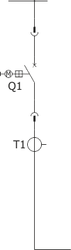
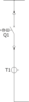
Sheet 1.1 - Feeder bay with circuit breaker, 12 kV
| Parameters: | ||
| Rated voltage | [kV] | 12 |
| Rated power-frequency withstand voltage | [kV] | 28 |
| Rated lightning impulse withstand voltage | [kV] | 75 |
| Rated frequency | [Hz] | 50 |
| Rated continuous current | [A] | 630-1250 |
| Main busbars rated cotinuous current | [A] | 630-1250 |
| Rated short-time withstand current | [kA/1s] | up to 25 |
| Rated peak withstand current | [kA] | up to 65 |
| Withstand for internal arcing fault | [kA/1s] | up to 25 |
| Protection degree | up to IP4X | |
| Equipment: | ||
| Circuit breaker | Q1 | VB-4 (ZPUE); SION (Siemens); VD4/HD4 (ABB); HVX (Schneider Electric) |
| Earthing switch | Q3 | US1 (ZPUE); EK6 (ABB) |
| Current transformer | T1 | various manufacturers |
| Voltage transformer | T2 | various manufacturers |
| Earth fault transformer | T4 | various manufacturers |
| Surge arrester | F1 | various manufacturers |
| Weight | [kg] | 560-700 |
| Note: We allow the possibility of arranging the bay configuration concerning its function and equipment (type/manufacturer) |
||
Sheet 1.2 - Feeder bay with circuit breaker and a separate compartment of main busbars, 12 kV
| Parameters: | ||
| Rated voltage | [kV] | 12 |
| Rated power-frequency withstand voltage | [kV] | 28 |
| Rated lightning impulse withstand voltage | [kV] | 75 |
| Rated frequency | [Hz] | 50 |
| Rated continuous current | [A] | 630-1250 |
| Main busbars rated cotinuous current | [A] | 630-1250 |
| Rated short-time withstand current | [kA/1s] | up to 25 |
| Rated peak withstand current | [kA] | up to 63 |
| Withstand for internal arcing fault | [kA/1s] | up to 25 |
| Protection degree | up to IP4X | |
| Equipment: | ||
| Circuit breaker | Q1 | VB-4 (ZPUE); SION (Siemens); VD4/HD4 (ABB); HVX (Schneider) |
| Earthing switch | Q3 | US1 (ZPUE); EK6 (ABB) |
| Current transformer | T1 | various manufacturers |
| Voltage transformer | T2 | various manufacturers |
| Surge arrester | F1 | various manufacturers |
| Weight | [kg] | 650 |
| Note: We allow the possibility of arranging the bay configuration concerning its function and equipment (type/manufacturer) |
||
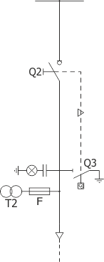
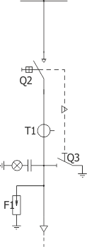
Sheet 1.4 - Feeder bay with switch disconnector, 12 kV
| Parameters: | ||
| Rated voltage | [kV] | 12 |
| Rated power-frequency withstand voltage | [kV] | 28 |
| Rated lightning impulse withstand voltage | [kV] | 75 |
| Rated frequency | [Hz] | 50 |
| Rated continuous current | [A] | 630-1250 |
| Main busbars rated cotinuous current | [A] | 630-1250 |
| Rated short-time withstand current | [kA/1s] | up to 25 |
| Rated peak withstand current | [kA] | up to 63 |
| Withstand for internal arcing fault | [kA/1s] | up to 25 |
| Protection degree | up to IP4X | |
| Equipment: | ||
| Switch disconnector | Q2 | NAL (ABB); OM (ZWAE) |
| Earthing switch | Q3 | fast, with an impulse drive |
| Voltage transformer | T2 | various manufacturers |
| Weight | [kg] | 520-620 |
| Note: We allow the possibility of arranging the bay configuration concerning its function and equipment (type/manufacturer) |
||
Sheet 1.6 - Bus coupler bay - cubicle with circuit breaker, 12 kV
| Parameters: | ||
| Rated voltage | [kV] | 12 |
| Rated power-frequency withstand voltage | [kV] | 28 |
| Rated lightning impulse withstand voltage | [kV] | 75 |
| Rated frequency | [Hz] | 50 |
| Rated continuous current | [A] | 630-1250 |
| Main busbars rated cotinuous current | [A] | 630-1250 |
| Rated short-time withstand current | [kA/1s] | up to 25 |
| Rated peak withstand current | [kA] | up to 63 |
| Withstand for internal arcing fault | [kA/1s] | up to 25 |
| Protection degree | up to IP4X | |
| Equipment: | ||
| Circuit breaker | Q1 | VB-4 (ZPUE); SION (Siemens); VD4/HD4 (ABB); HVX (Schneider Electric); |
| Current transformer | T1 | various manufacturers |
| Weight | [kg] | 530-630 |
| Note: We allow the possibility of arranging the bay configuration concerning its function and equipment (type/manufacturer) |
||
Sheet 1.8 - Bus coupler bay - cubicle with sectionalizer, 12 kV


| Parameters: | ||
| Rated voltage | [kV] | 12 |
| Rated power-frequency withstand voltage | [kV] | 28 |
| Rated lightning impulse withstand voltage | [kV] | 75 |
| Rated frequency | [Hz] | 50 |
| Rated continuous current | [A] | 630-1250 |
| Main busbars rated cotinuous current | [A] | 630-1250 |
| Rated short-time withstand current | [kA/1s] | up to 25 |
| Rated peak withstand current | [kA] | up to 63 |
| Withstand for internal arcing fault | [kA/1s] | up to 25 |
| Protection degree | up to IP4X | |
| Equipment: | ||
| Sectionalizer | Q4 | made by ZPUE |
| Weight | [kg] | 405-510 |
| Note: We allow the possibility of arranging the bay configuration concerning its function and equipment (type/manufacturer) |
||
Sheet 1.10 - Metering bay, 12 kV
| Parameters: | ||
| Rated voltage | [kV] | 12 |
| Rated power-frequency withstand voltage | [kV] | 28 |
| Rated lightning impulse withstand voltage | [kV] | 75 |
| Rated frequency | [Hz] | 50 |
| Main busbars rated cotinuous current | [A] | 630-1250 |
| Rated short-time withstand current | [kA/1s] | up to 25 |
| Rated peak withstand current | [kA] | up to 63 |
| Withstand for internal arcing fault | [kA/1s] | up to 25 |
| Protection degree | up to IP4X | |
| Equipment: | ||
| Withdrawal module | withdrawable module with voltage transformers | |
| Earthing switch | Q3 | US1 (ZPUE); EK6 (ABB) |
| Voltage transformer | T2 | various manufacturers |
| Weight | [kg] | 440-540 |
| Note: We allow the possibility of arranging the bay configuration concerning its function and equipment (type/manufacturer) |
||
Sheet 1.11 - Metering bay with a separate compartment of main busbars, 12 kV

| Parameters: | ||
| Rated voltage | [kV] | 12 |
| Rated power-frequency withstand voltage | [kV] | 28 |
| Rated lightning impulse withstand voltage | [kV] | 75 |
| Rated frequency | [Hz] | 50 |
| Main busbars rated cotinuous current | [A] | 630-1250 |
| Rated short-time withstand current | [kA/1s] | up to 25 |
| Rated peak withstand current | [kA] | up to 63 |
| Withstand for internal arcing fault | [kA/1s] | up to 25 |
| Protection degree | up to IP4X | |
| Equipment: | ||
| Withdrawal module | withdrawable module with voltage transformers | |
| Earthing switch | Q3 | US1 (ZPUE); EK6 (ABB) |
| Voltage transformer | T2 | various manufacturers |
| Weight | [kg] | 470 |
| Note: We allow the possibility of arranging the bay configuration concerning its function and equipment (type/manufacturer) |
||
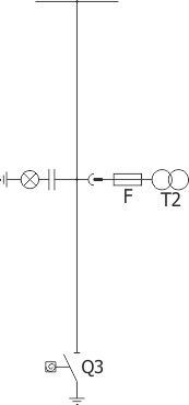
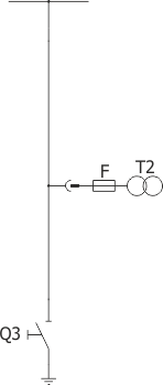
Sheet 1.13 - Auxiliary transformer bay - with a transformer up to 40 kVA, 6/0.4 kV

| Parameters: | ||
| Rated voltage | [kV] | 12 |
| Rated power-frequency withstand voltage | [kV] | 28 |
| Rated lightning impulse withstand voltage | [kV] | 75 |
| Rated frequency | [Hz] | 50 |
| Main busbars rated cotinuous current | [A] | 630-1250 |
| Rated short-time withstand current | [kA/1s] | up to 25 |
| Rated peak withstand current | [kA] | up to 63 |
| Withstand for internal arcing fault | [kA/1s] | up to 25 |
| Protection degree | up to IP4X | |
| Equipment: | ||
| Switch disconnector | Q2 | NALF (ABB); OMB (ZWAE) |
| Transformer | T | up to 40 kVA; 6/0,4 kV |
| Weight | [kg] | 890 |
| Notice: We allow the possibility of arranging the bay configuration concerning its function and equipment (type/manufacturer) |
||
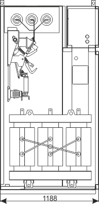
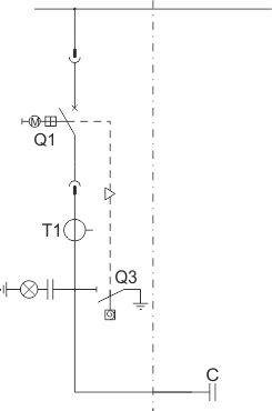
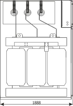
Sheet 1.14 - Reactive power compensation set - with a capacitor bank up to 700 kvar; 6.6 kV
| Parameters: | ||
| Rated voltage | [kV] | 12 |
| Rated power-frequency withstand voltage | [kV] | 28 |
| Rated lightning impulse withstand voltage | [kV] | 75 |
| Rated frequency | [Hz] | 50 |
| Main busbars rated cotinuous current | [A] | 630-1250 |
| Rated short-time withstand current | [kA/1s] | up to 25 |
| Rated peak withstand current | [kA] | up to 63 |
| Withstand for internal arcing fault | [kA/1s] | up to 25 |
| Protection degree | up to IP4X | |
| Equipment: | ||
| Circuit breaker/contactor | Q1 | VB-4 (ZPUE); SION (Siemens); VD4/HD4 (ABB); HVX (Schneider Electric); 3TM (Siemens), ConVac (ABB) |
| Earthing switch | Q3 | US1 (ZPUE); EK6 (ABB) |
| Current transformer | T1 | various manufacturers |
| Capacitor bank | C | up to 700 kvar; 6,6 kV |
| Weight | [kg] | 960 |
| Note: We allow the possibility of arranging the bay configuration concerning its function and equipment (type/manufacturer) |
||
RXD 36 kV
| RXD 36 kV | ||
| 1. | Sheet 2.1 | Feeder bay with circuit breaker |
| 2. | Sheet 2.2 | Feeder bay with switch disconnector |
| 3. | Sheet 2.3 | Bus coupler bay - cubicle with circuit breaker |
| 4. | Sheet 2.4 | Bus coupler bay - cubicle with sectionalizer |
| 5. | Sheet 2.5 | Metering bay |
| 6. | Sheet 2.6 | Auxiliary transformer bay |
| * These data sheets are exemplary solutions which can be changed. In case of switchgears with technical parameters and bay configurations different than the ones presented, appropriate data sheets are available directly from the manufacturer or on the www.zpue.com website. | ||
Sheet 2.1 - Feeder bay with circuit breaker
| Parameters: | |||
| Rated voltage | [kV] | 36 | |
| Rated power-frequency withstand voltage | to earth and between phases | [kV] | 85 (5min) / 95 (1min) |
| across the isolating distance | [kV] | 120 (5min) | |
| Rated lightning impulse withstand voltage | to earth and between phases | [kV] | 190 (1,2/50µs) |
| across the isolating distance | [kV] | 220 (1,2/50µs) | |
| Rated frequency | [Hz] | 50 | |
| Rated continuous current | [A] | 630 | |
| Main busbars rated cotinuous current | [A] | 630 | |
| Rated short-time withstand current | [kA/1s] | up to 25 | |
| Rated peak withstand current | [kA] | up to 63 | |
| Withstand for internal arcing fault | [kA/1s] | up to 20 | |
| Protection degree | up to IP4X | ||
| Equipment: | ||
| Circuit breaker | Q1 | 3AH (SIEMENS); VD4/HD4 (ABB) |
| Earthing switch | Q3 | UW36 |
| Current transformer | T1 | various manufacturers |
| Voltage transformer | T2 | various manufacturers |
| Overvoltage limiter | F1 | various manufacturers |
| Weight | [kg] | 1380 |
| Note: We allow the possibility of arranging the bay configuration concerning its function and equipment (type/manufacturer) |
||
Sheet 2.2 - Feeder bay with switch disconnector
| Parameters: | |||
| Rated voltage | [kV] | 36 | |
| Rated power-frequency withstand voltage | to earth and between phases | [kV] | 85 (5min) / 95 (1min) |
| across the isolating distance | [kV] | 120 (5min) | |
| Rated lighting impulse withstand voltage | to earth and between phases | [kV] | 190 (1,2/50µs) |
| across the isolating distance | [kV] | 220 (1,2/50µs) | |
| Rated frequency | [Hz] | 50 | |
| Rated continuous current | [A] | 630 | |
| Main busbars rated cotinuous current | [A] | 630 | |
| Rated short-time withstand current | [kA/1s] | up to 25 | |
| Rated peak withstand current | [kA] | up to 63 | |
| Withstand for internal arcing fault | [kA/1s] | up to 20 | |
| Protection degree | up to IP4X | ||
| Equipment: | ||
| Switch disconnector | Q2 | NAL 36 (ABB) |
| Earthing switch | Q3 | UW36 |
| Current transformer | T1 | various manufacturers |
| Overvoltage limiter | F1 | various manufacturers |
| Weight | [kg] | 1150 |
| Note: We allow the possibility of arranging the bay configuration concerning its function and equipment (type/manufacturer) |
||
Sheet 2.3 - Bus coupler bay - cubicle with circuit breaker

| Parameters: | |||
| Rated voltage | [kV] | 36 | |
| Rated power-frequency withstand voltage | to earth and between phases | [kV] | 85 (5min) / 95 (1min) |
| across the isolating distance | [kV] | 120 (5min) | |
| Rated lighting impulse withstand voltage | to earth and between phases | [kV] | 190 (1,2/50µs) |
| across the isolating distance | [kV] | 220 (1,2/50µs) | |
| Rated frequency | [Hz] | 50 | |
| Rated continuous current | [A] | 630 | |
| Main busbars rated cotinuous current | [A] | 630 | |
| Rated short-time withstand current | [kA/1s] | up to 25 | |
| Rated peak withstand current | [kA] | up to 63 | |
| Withstand for internal arcing fault | [kA/1s] | up to 20 | |
| Protection degree | up to IP4X | ||
| Equipment: | ||
| Circuit breaker | Q1 | 3AH (SIEMENS); VD4/HD4 (ABB) |
| Current transformer | T1 | various manufacturers |
| Weight | [kg] | 1300 |
| Notice: We allow the possibility of arranging the bay configuration concerning its function and equipment (type/manufacturer) |
||
Sheet 2.4 - Bus coupler bay - cubicle with sectionalizer


| Parameters: | |||
| Rated voltage | [kV] | 36 | |
| Rated power-frequency withstand voltage | to earth and between phases | [kV] | 85 (5min) / 95 (1min) |
| across the isolating distance | [kV] | 120 (5min) | |
| Rated lighting impulse withstand voltage | to earth and between phases | [kV] | 190 (1,2/50µs) |
| across the isolating distance | [kV] | 220 (1,2/50µs) | |
| Rated frequency | [Hz] | 50 | |
| Rated continuous current | [A] | 630 | |
| Main busbars rated cotinuous current | [A] | 630 | |
| Rated short-time withstand current | [kA/1s] | up to 25 | |
| Rated peak withstand current | [kA] | up to 63 | |
| Withstand for internal arcing fault | [kA/1s] | up to 20 | |
| Protection degree | up to IP4X | ||
| Equipment: | ||
| Sectionalizer | Q4 | made by ZPUE |
| Weight | [kg] | 1150 |
| Note: We allow the possibility of arranging the bay configuration concerning its function and equipment (type/manufacturer) |
||
Sheet 2.5 - Metering bay
| Parameters: | |||
| Rated voltage | [kV] | 36 | |
| Rated power-frequency withstand voltage | to earth and between phases | [kV] | 85 (5min) / 95 (1min) |
| across the isolating distance | [kV] | 120 (5min) | |
| Rated lighting impulse withstand voltage | to earth and between phases | [kV] | 190 (1,2/50µs) |
| across the isolating distance | [kV] | 220 (1,2/50µs) | |
| Rated frequency | [Hz] | 50 | |
| Main busbars rated cotinuous current | [A] | 630 | |
| Rated short-time withstand current | [kA/1s] | up to 25 | |
| Rated peak withstand current | [kA] | up to 63 | |
| Withstand for internal arcing fault | [kA/1s] | up to 20 | |
| Protection degree | up to IP4X | ||
| Equipment: | ||
| Withdrawable module | withdrawable module with voltage transformers | |
| Earthing switch | Q3 | UW36 |
| Voltage transformer | T2 | various manufacturers |
| Weight | [kg] | 1100 |
| Note: We allow the possibility of arranging the bay configuration concerning its function and equipment (type/manufacturer) |
||
Sheet 2.6 - Auxiliary transformer bay

| Parameters: | |||
| Rated voltage | [kV] | 36 | |
| Rated power-frequency withstand voltage | to earth and between phases | [kV] | 85 (5min) / 95 (1min) |
| across the isolating distance | [kV] | 120 (5min) | |
| Rated lighting impulse withstand voltage | to earth and between phases | [kV] | 190 (1,2/50µs) |
| across the isolating distance | [kV] | 220 (1,2/50µs) | |
| Rated frequency | [Hz] | 50 | |
| Main busbars rated cotinuous current | [A] | 630 | |
| Rated short-time withstand current | [kA/1s] | up to 25 | |
| Rated peak withstand current | [kA] | up to 63 | |
| Withstand for internal arcing fault | [kA/1s] | up to 20 | |
| Protection degree | up to IP4X | ||
| Equipment: | ||
| Disconnector/Switch disconnector | Q2 | ON/NAL (ABB) |
| Transformer | T | up to 100 kVA; 35/0,4 kV |
| Weight | [kg] | 2070 |
| Note: We allow the possibility of arranging the bay configuration concerning its function and equipment (type/manufacturer) |
||